Ampcontrol Pty Ltd
– ABN 28 000 915 542
PF1 USER MANUAL
MAG-165 Version 6
– March/2020
Uncontrolled Copy - Refer to Ampcontrol Website for Latest Version
Page 24 of 71
A
P
P
R
OV
E
D
FOR
E
X
T
E
R
N
A
L
D
IS
TR
IB
U
T
ION
–
P
R
OP
E
R
T
Y
OF
A
M
P
C
ON
TR
OL
P
T
Y
LTD
–
N
O
T
T
O
B
E
R
E
P
R
OD
U
C
E
D
I
N
P
A
R
T
5
COMMISSIONING
Prior to being put into service, the electrical protection system must be correctly commissioned. This
manual does not cover system commissioning; the full scope of commissioning tests should be
determined during the risk assessment or FMEA covering the design of the electrical protection system.
The following tests can provide guidance on checking the correct operation of the PF1 during
commissioning. This is not intended to provide an exhaustive commissioning checklist, but should be
considered to be a minimum set of tests.
Each test need only be completed if that particular function of the PF1 is being utilised in the installation.
5.1 Pump Protection Test
Required if: Pump Protection is enabled.
Using the Smart Tools software, configure the operational settings of the pump outlet.
Required if: Pump Sleep Mode is enabled.
Prior to commencement of general operation, the iSet procedure must be completed.
This procedure is required for each PF1 (+pump), which has been configured with a fixed or incremental
pump sleep mode.
For instructions on performing the iSet procedure, refer to Section 6.1.3.
5.2 Fan Protection Test
Required if: Fan Protection is enabled.
Using the Smart Tools software, configure the operational settings of the fan outlet.
5.3 Earth Leakage Test
Required if: Earth Leakage Protection is enabled.
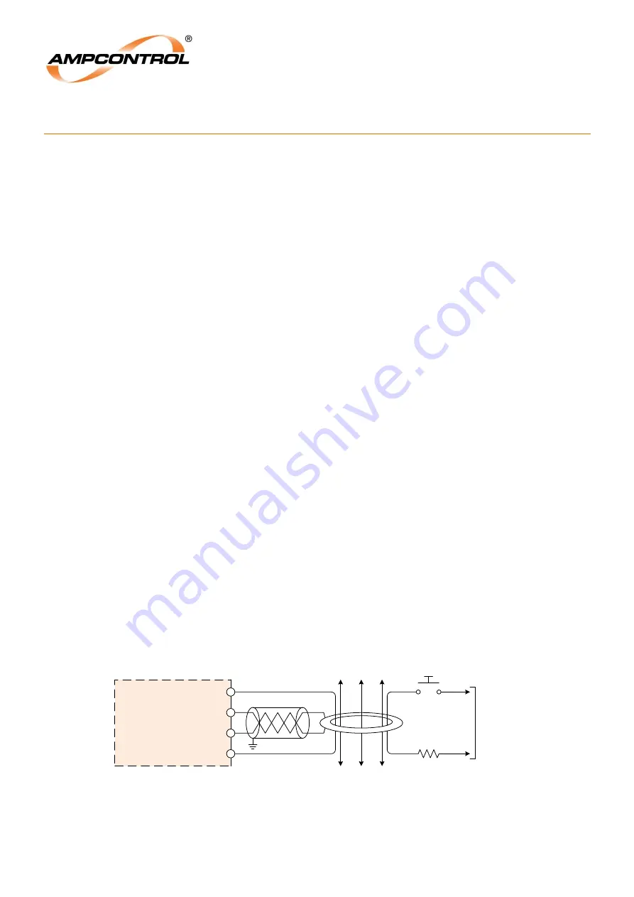
In order to test that the earth leakage protection is functioning correctly, with the outlet running, inject a
test current at 120% of the trip level setting through the centre of the toroid.
Confirm that the PF1
trips on an earth leakage fault and the outlet’s main contactor is opened. The red
“Trip” LED on the fascia of the PF1 should be illuminated.
This test will verify that the earth leakage toroid is functioning and is wired in correctly, as well as proving
that the K1 output relay trips the main contactor when an earth leakage fault is detected.
PF1
RELAY
25
26
28
29
S1
S2
EL Test 1
EL Test 2
A
B
C
Test Resistor
E/L Test
Push Button
To
Test Supply
Earth Leakage Test
EL S1
EL S2
Figure 5.1: Earth Leakage Test Wiring


