background image

INTRODUCTION

The ILD15 has been designed as a high quality stand-alone induction loop driver 
for use in small to medium size lifts, although the rugged construction may be 
suited to other industrial applications.

The unit is designed to drive a loop constructed out of custom built metal bars, 
which is a very low impedance. Ordinary wire can sometimes be used if it can be 
installed inside the lift car, but care must be taken to ensure the loop satisfies the 
unit’s load requirements.

The ILD15 comes in a number of different versions 

All versions have:

#

two separate audio inputs, 

#

230V or 115V AC power supply (factory set option) 

#

transformer coupled loop output. 

The standard unit has one low-Z speaker line level input and one 100V PA line 
input.

Unit versions are indicated by the suffix:

#

BB - Battery back-up (If AC power fails, battery powers unit). 

#

NB - No battery back-up. 

#

BBL / NBL - As above, but two line level / low Z speaker inputs (and no 100V 
PA line input).

All connections (except the ‘Protective Earth Terminal’) are via vibration-resistant 
cage clamp terminals which are quick and easy to connect. 

QUICK START

1. Fit ILD15 on top of lift where it will not be vulnerable to damage and where 

the cables will be protected.

2. Fit loop cable / bars (refer to fitting section) 

Ensure loop is insulated from lift body.

3. Connect loop to amplifier using feed cables. Ensure feed pair is twisted 

together.

4. Connect Signal Inputs 

(see input connection drawings)

 using twisted pair 

cable.

5. Connect AC power

 (see points 5 and 8 in Safety section)

6. Turn ‘Gain 1’, ‘Gain 2’, and ‘Drive’ controls fully anticlockwise (minimum), and 

the ‘loss’ control to centre setting.

7. Switch on external power:-

!

(Not ‘NB’ or ‘NBL’  version) 

8. Operate internal switch SW2 

( not fitted on ‘NB’ or ‘NBL’  version)

!

Check Green ‘Power’ LED illuminates.

10. Apply input signal (eg intercom). Increase the input control until the Green 

‘Compression’ LED  begins to light.

11. Repeat item10 for the second input (if used). 

Only apply one audio signal at 

a time when setting up the system.

12. Adjust the DRIVE control until the Yellow ‘Loop Current’ LED lights at peaks 

in the input signal.   

NOTE: Once the DRIVE control is set, do not adjust it 

again.

Check Yellow ‘Battery Charge’ or Green ‘Battery Float’ LED illuminates. 
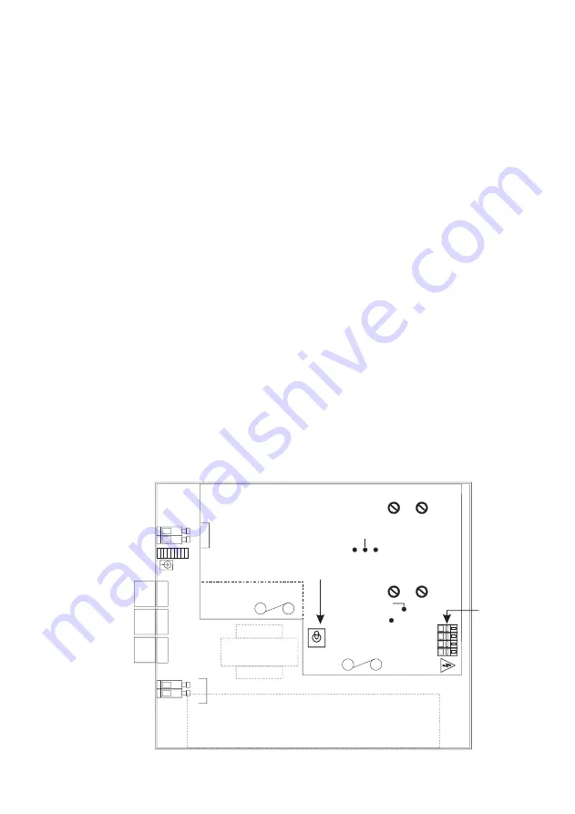
LOOP

AC

POWER

SW2

INPUT 1

INPUT 2

DRIVE

LOSS

COMPRESSION

LOOP CURRENT

POWER

INPUT 2

INPUT 1

In

s

e

rt

 s

c

re

w

d

ri

v

e

r

to

 o

p

e

n

 c

o

n

ta

c

t

BATTERY CHARGE 
   
 BATTERY FLOAT

Push plunger
to open contact
before inserting wire.

Push plunger
to open contact
before inserting wire.

AC
POWER 
CABLE

AUDIO 
INPUT

LOOP
CABLE

C

a

b

le

s

 m

u

s

b

e

 k

e

p

in

s

e

p

a

ra

te

 b

u

s

h

in

g

s

 D

o

 n

o

m

ix

 c

a

b

le

s

 —

AC POWER FUSE
Under insulating barrier

OFF

NORMAL

BATTERY FUSE

N

L

E

Layout

Basic Wiring

Audio Input signal

Switched
& fused 
power
source

Loop

Twisted Pair 
Cable to Loop

ILD15

Summary of Contents for ILD15 Series

Page 1: ... APPARATUS MUST BE EARTHED 5 The ILD15 is designed to be permanently connected apparatus and must be installed with all applicable installation regulations A readily accessible disconnect device shall be incorporated in the building installation power wiring 6 Mount the ILD15 with the wiring entering from the side of the unit Position cables in a neat manner and tighten the cable clamps to ensure ...

Page 2: ...15 comes in a number of different versions All versions have two separate audio inputs 230V or 115V AC power supply factory set option transformer coupled loop output The standard unit has one low Z speaker line level input and one 100V PA line input Unit versions are indicated by the suffix BB Battery back up If AC power fails battery powers unit NB No battery back up BBL NBL As above but two lin...

Page 3: ...es 10 Apply input signal eg intercom Increase the input control until the Green Compression LED begins to light 11 Repeat item10 for the second input if used Only apply one audio signal at a time when setting up the system 12 Adjust the DRIVE control until the Yellow Loop Current LED lights at peaks in the input signal NOTE Once the DRIVE control is set do not adjust it again Check Yellow Battery ...

Page 4: ...e Power LED Power input Input 1 Input 2 AC Input Version MLC AGC Battery charger DC power to system Charge Float Twist together Low Z Speaker feed Inputs BB NB Versions 100V speaker line Input 2 Input 1 ILD15 I P1 ILD15 I P2 Twist together Twist together Low Z Speaker feed Low Z Speaker feed Input 1 Input 2 Inputs BBL NBL Versions ILD15 I P1 ILD15 I P2 ...

Page 5: ...ect the loop cable ends to the loop output connector make sure that the feed cable the 2 wire section between the amplifier and loop is tightly twisted together and less than 3m in length In lifts the loop connecting wires 2 should not be less than 2 5mm AWG 12 area See below for loop design INPUTS Connect inputs as shown in the diagram Note that input 2 is different on the ILD15BB and BBL Use Low...

Page 6: ...st control as appropriate 5 Turn the Drive control clockwise until the Loop Current LED lights at peaks in the input signal Once set there is no need to adjust the Drive control again 6 Repeat item 4 for the other input if used When adjusting each input make sure that audio signal s are removed from the other inputs This ensures that all signals are set to equivalent loudness and are operating the...

Page 7: ...Earthed Frequency Response Use the crimp terminal provided 80Hz 5 0kHz 1 5dB at low level measured as loop current with no MLC Inputs Transformer isolated 1500Vac minimum MLC Metal Loss Correction floating input 0 dB to 4dB Octave boost Connection via vibration proof cage clamp Fully anticlockwise flat response terminals Battery back up BB BBL versions Line level Low Z speaker input Internal 12V 2...

Page 8: ...attery is only covered by a 1 year warranty Manufacturer Ampetronic Ltd Northern Road Newark Nottinghamshire NG24 2ET United Kingdom Declares that the product Description Induction Loop Driver Type name ILD15BB NB BBL Conforms to the following Directive s and Norm s Directive 2004 108 EC EMC EN55103 1 1997 Emission EN55103 2 1997 Immunity Directive 2006 95 EC Safety EN60065 2002 Date Jan 2009 Leon...

Reviews: