background image

INSTALLATION

Tools

You will require the following:

!

Phillips screwdriver

!

Small flat blade screwdriver

!

Ratchet crimp tool

Location

The amplifier should be mounted where :

!

it is protected from drips or sprays of water

!

it is not vulnerable to mechanical damage

!

the controls can be accessed through the open cover.

The unit must be close to the loop; when used on a lift, it is typically mounted on 
top of the lift car.

Cable glands

The ILD15 is supplied with three cable glands to firmly clamp the cables entering 
the unit. The AC power, audio inputs & loop output cables should be fed through 
the case separately as shown in ‘

Basic Wiring

’.  The unit is designed to provide 

protection to IP43. This is subject to round wires between 5 and 10mm diameter 
being used. Suitable sleeving should be fitted to twisted pair or smaller cables to 
enlarge them to within this range.

To further prevent ingress run cables along the mounting surface then up into the 
cable glands

Connections

GENERAL:  Open the cage clamp terminals using a flat bladed screwdriver. See 

Layout


drawing for location of each terminal and details of its operation.

LOOP:  Connect the loop cable ends to the loop output connector. make sure that 

the feed cable (the 2-wire section between the amplifier and loop) is tightly 
twisted together and less than 3m in length. In lifts, the loop connecting wires 

2

should not be less than 2.5mm  (AWG 12) area. See below for loop design

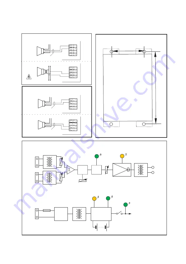
INPUTS:  Connect inputs as shown in the diagram. Note that input 2 is different on 

the ILD15BB and BBL. Use Low-Z connection for Intercom Speakers, Voice 
Announcers, etc, and 100V line for building PA. 

For all inputs, use twisted pair cables, preferably with screen.
AC POWER:  

The ILD15 can be supplied in 115VAC or 230VAC versions. 

Check that the version you have is compatible with your power supply.

Isolate external AC power source before working on power connections  

Use the crimp terminal, washer & nut provided to connect incoming AC Earth 

   OPERATION   (

see ‘Layout’ drawing for control names & positions)

1. Turn ‘Gain 1’, ‘Gain 2’ and ‘Drive’ controls fully anti-clockwise. 

 Set ‘MLC’ control to mid-position.

2. Switch on external AC power 

!

Check ‘Battery Charge’ or ‘Battery Float’ LED illuminates. 

(Not ‘NB’ version) 

3. Set internal switch SW2 to ‘Normal’ 

(Not fitted on ‘NB’ version)


!

Check Green ‘Power’ LED illuminates.

4. Apply an audio signal to one input 

(e.g. speech through an intercom). 

Turn the 

associated Gain control clockwise until Green ‘Compression’ LED illuminates.

Mo n ing De ai s

u t


t l

160mm

4

0

m

m

2

Top
View

Block Diagram

Compression LED

Output Current LED

Output

MLC Adjust

Drive

Loop
output

115V
230V
Select

Fuse

Power LED

Power
input

Input 1

Input 2

AC Input Version

MLC

AGC

Battery

charger

DC power to

system

Charge

Float

Twist together

Low Z Speaker feed

Inputs

BB & NB Versions

100V speaker line

Input 2

Input 1

ILD15

I/P

1

ILD15

I/P

2

Twist together

Twist together

Low Z Speaker feed

Low Z Speaker feed

Input 1

Input 2

Inputs

BBL & NBL Versions

ILD15

I/P

1

ILD15

I/P

2

Summary of Contents for ILD15 Series

Page 1: ... APPARATUS MUST BE EARTHED 5 The ILD15 is designed to be permanently connected apparatus and must be installed with all applicable installation regulations A readily accessible disconnect device shall be incorporated in the building installation power wiring 6 Mount the ILD15 with the wiring entering from the side of the unit Position cables in a neat manner and tighten the cable clamps to ensure ...

Page 2: ...15 comes in a number of different versions All versions have two separate audio inputs 230V or 115V AC power supply factory set option transformer coupled loop output The standard unit has one low Z speaker line level input and one 100V PA line input Unit versions are indicated by the suffix BB Battery back up If AC power fails battery powers unit NB No battery back up BBL NBL As above but two lin...

Page 3: ...es 10 Apply input signal eg intercom Increase the input control until the Green Compression LED begins to light 11 Repeat item10 for the second input if used Only apply one audio signal at a time when setting up the system 12 Adjust the DRIVE control until the Yellow Loop Current LED lights at peaks in the input signal NOTE Once the DRIVE control is set do not adjust it again Check Yellow Battery ...

Page 4: ...e Power LED Power input Input 1 Input 2 AC Input Version MLC AGC Battery charger DC power to system Charge Float Twist together Low Z Speaker feed Inputs BB NB Versions 100V speaker line Input 2 Input 1 ILD15 I P1 ILD15 I P2 Twist together Twist together Low Z Speaker feed Low Z Speaker feed Input 1 Input 2 Inputs BBL NBL Versions ILD15 I P1 ILD15 I P2 ...

Page 5: ...ect the loop cable ends to the loop output connector make sure that the feed cable the 2 wire section between the amplifier and loop is tightly twisted together and less than 3m in length In lifts the loop connecting wires 2 should not be less than 2 5mm AWG 12 area See below for loop design INPUTS Connect inputs as shown in the diagram Note that input 2 is different on the ILD15BB and BBL Use Low...

Page 6: ...st control as appropriate 5 Turn the Drive control clockwise until the Loop Current LED lights at peaks in the input signal Once set there is no need to adjust the Drive control again 6 Repeat item 4 for the other input if used When adjusting each input make sure that audio signal s are removed from the other inputs This ensures that all signals are set to equivalent loudness and are operating the...

Page 7: ...Earthed Frequency Response Use the crimp terminal provided 80Hz 5 0kHz 1 5dB at low level measured as loop current with no MLC Inputs Transformer isolated 1500Vac minimum MLC Metal Loss Correction floating input 0 dB to 4dB Octave boost Connection via vibration proof cage clamp Fully anticlockwise flat response terminals Battery back up BB BBL versions Line level Low Z speaker input Internal 12V 2...

Page 8: ...attery is only covered by a 1 year warranty Manufacturer Ampetronic Ltd Northern Road Newark Nottinghamshire NG24 2ET United Kingdom Declares that the product Description Induction Loop Driver Type name ILD15BB NB BBL Conforms to the following Directive s and Norm s Directive 2004 108 EC EMC EN55103 1 1997 Emission EN55103 2 1997 Immunity Directive 2006 95 EC Safety EN60065 2002 Date Jan 2009 Leon...

Reviews: