Amphenol Network Solutions
All rights reserved. 12.17.19 146161-3
509.926.6000 — amphenol-ns.com.com
High-Current
Demarcation Panel
9
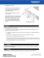
3. If necessary, to move or replace the 19-inch
brackets, remove three screws on sides of
breaker panel, as shown in Fig. 4.
4. Install 19-inch or 23-inch brackets for flush
or extended panel presentation on rack.
5. Locate an unused rack position and mount
panel using the four thread-cutting screws
provided, as shown in Fig. 5. Tighten the
screws to 35 in/lb. (4.29 N
•
m).
6. Use a UL/NRTL-approved crimping tool
to attach a UL/NRTL-approved, 2-hole
compression lug onto a #10 to #2 AWG
ground wire. (The size of the ground wire
depends on size of input BATT wires.)
7. Attach the opposite end of the ground wire
to the relay rack, per local practices.
8. If required, lightly coat antioxidant on lug,
grounding terminal and contacting surface.
9. Connect the lug to the terminal using the nuts
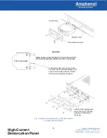
and washers (supplied), refer to Fig. 6.
10. Tighten the nut to 36 in/lb. (4 N
•
m).
NOTE: Input and output wire size for this panel
must be rated for the corresponding breaker/fuse
size at the power distribution unit (PDU). The input
wiring to this panel may be a greater size to
accommodate a voltage drop from the primary
power source.
NOTE: Always follow operating company guidelines
when connecting input wiring to the primary power
source.
11. Make sure the input power is OFF.
12. For input wiring, crimp straight or angled, 2-hole
compression lugs onto #8 to #1 copper wires.
Insulate lug barrels with UL94 V-0 rated heat
shrink tubing.
One of Two Universal
(Right or Left) 23 in.
Rack Brackets
Right-Hand 19 in.
Rack Bracket
Holes for Flush
Mounting Panel
to Rack
One of Seven Sets of Rack
Bracket Mounting Holes for
Extending Front of Panel in 1-
inch increments
Fig. 4: Bracket orientation
Fig. 5: Rack mounting
Fig. 6: Ground lug connection


