background image

2/4 

2022/04/25  Rev.01  Document No: 8P1164 

HV  二芯连接器组装说明  2 POS HV Flange Connector Assembly Manual 

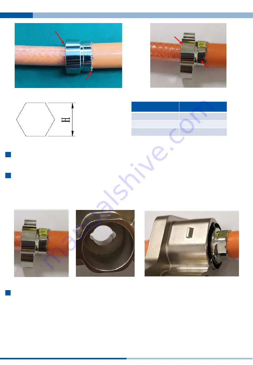
与外被口平齐 

Flush with the 

jacket 

编织不超出铜套1mm 

Braiding does not exceed 

1mm from pressure ring 

后套上的屏蔽环 

Shielded ring assemble on 

the next step 

压接区 

Crimp area 

线材尺寸 

Cable Size 

H(mm) 

35mm² 

15.5±0.5 

50mm² 

18.0±0.5 

70mm² 

19.8±0.5 

正六边压接 

Hexagonal 

crimping 

步骤4:客户根据所选端子要求压接好端子,推荐芯线压缩比为80~90%。 

Step 4: Crimp the terminal as required. The recommended conductor compression ratio is 80 to 90%. 

步骤5:将HV连接器所带的接触环卡住铜套前端,取一根线穿入接头主体PIN B,轻压屏蔽环两翼, 
塞入接头金属壳中如图示。 

Step 5: Stick the shielded ring of the HV connector to the front end of the pressure ring, take a cable and put 

it into the connector main body PIN B, and gently press the two wings of the shielding ring, Insert into metal 

shell of connector as shown. 

步骤6:将线材上的密封胶套、后密封圈与尾盖顺次压紧装入HV金属壳中。 

Step 6: Put the cushion ring, rear sealing ring and end cap on the wire into the HV metal shell successively. 

Summary of Contents for HV Series

Page 1: ...www amphenol gec com HV 二芯连接器组装说明 Document No 8P1164 Rev 02 2 POS HV Flange Connector Assembly Manual 键位 X 键 Y 键 Key X Y 线缆大小 Cable Size mm2 35 50 70 HVB321 X XX ...

Page 2: ...ength B mm 根据客户端子 According to terminal of customer L 12mm 步骤2 将HV连接器所带的图示配件分别套入两根线材中 Step 2 Insert the illustrated accessories of the HV connector into the two cables 密封胶套 Cushion Ring 后密封圈 Rear sealing ring 尾盖 End Cap 大开口朝向线端 Large opening towards the striped end 步骤3 将HV连接器所带的压接铜套套入线材屏蔽反折处 铜套边缘与外被口平齐 用免换模压接机压紧它 压完 后铜套不应移位 拉力大于150N 注意压接位置正确 推荐压接高度参照下页 Step 3 Put the Pressure ring of the HV connec...

Page 3: ... 推荐芯线压缩比为80 90 Step 4 Crimp the terminal as required The recommended conductor compression ratio is 80 to 90 步骤5 将HV连接器所带的接触环卡住铜套前端 取一根线穿入接头主体PIN B 轻压屏蔽环两翼 塞入接头金属壳中如图示 Step 5 Stick the shielded ring of the HV connector to the front end of the pressure ring take a cable and put it into the connector main body PIN B and gently press the two wings of the shielding ring Insert into metal shell of conn...

Page 4: ...lace HV 二芯连接器组装说明 2 POS HV Flange Connector Assembly Manual 2022 05 03 Rev 02 Document No 8P1164 步骤7 重复以上步骤组装好 PIN A 的线材 Step 7 Repeat the above steps to assemble the PIN A cable 步骤8 如图示在接头上套上二个前密封圈 Step 8 Insert two front sealing rings on the connector as shown ...

Page 5: ...5 18 5mm 70mm 14 5 0 4 19 1 0 5 18 5mm AC CP001460 HV 二芯连接器组装说明 2 POS HV Flange Connector Assembly Manual 2022 05 03 Rev 02 Document No 8P1164 Recommended screw assembly torque on flange 6 2 7 6 N m Refer to the following table for cable dimensions and terminal dimensions 版本记录 Revision history 序号 Number 版本 Rev 变更内容 Content of change 日期 Date 1 01 新出 New issue 2022 04 25 2 02 由中文版更改为中英文版 From Chines...

Page 6: ...any such use is free of patent infringement and are not recommendations to infringe any patent Specifications are typical and may not apply to all connectors Note that these specifications are derived from relevant global standards used in the automotive and industrial transportation markets but they are not a substitute for system level design validation testing which is the sole responsibility o...

Reviews: