
17
Temposonics
®
GB-Series SSI
Operation Manual
5/
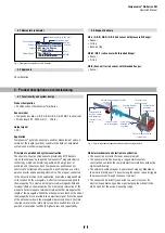
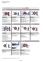
Follow the manufacturer‘s mounting instructions
Controlling design dimensions are in millimeters and measurements in ( ) are in inches
Manuals, Software & 3D Models available at:
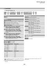
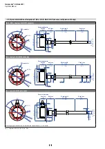
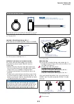
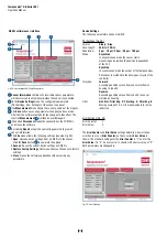
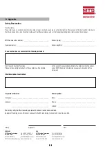
Cable connectors
5
~ 60
(~ 2.36)
M12
×1
Ø 20 (
Ø
0.79)
20
(0.79)
~ 57
(~ 2.24)
38 (1.5)
54
(2.13)
Ø
18
(Ø 0.71)
~ 54
(~2.13)
~ 38 (~ 1.5)
Ø 20.5
(Ø 0.81)
Ø 18
(Ø 0.71)
M12 A-coded female connector
(8 pin), straight
Part no. 370 694
M12 A-coded female connector
(8 pin), angled
Part no. 370 699
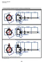
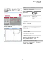
M16 female connector (7 pin), straight
Part no. 370 624
M16 female connector (7 pin), angled
Part no. 560 779
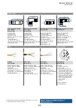
Housing: GD-ZnAL
Termination: Screw
Contact insert: CuZn
Cable Ø: 4…9 mm (0.16…0.35 in.)
Wire: 0.75 mm
2
Operating temperature:
−25…+90 °C (−13…+194 °F)
Ingress protection: IP67 (correctly fi tted)
Fastening torque: 0.6 Nm
Housing: GD-ZnAL
Termination: Screw
Contact insert: CuZn
Cable Ø: 6…8 mm (0.24…0.31 in.)
Wire: 0.5 mm
2
Operating temperature:
−25…+85 °C (−13…+185 °F)
Ingress protection: IP67 (correctly fi tted)
Fastening torque: 0.6 Nm
Material: Zinc nickel plated
Termination: Solder
Contact insert: Silver plated
Cable clamp: PG9
Cable Ø: 6…8 mm (0.24…0.31 in.)
Operating temperature:
−40…+100 °C (−40…+212 °F)
Ingress protection: IP65 / IP67
(correctly fi tted)
Fastening torque: 0.7 Nm
Material: Zinc nickel plated
Termination: Solder
Contact insert: Silver plated
Cable Ø: 6…8 mm (0.24…0.31 in.)
Wire: 0.75 mm² (20 AWG)
Operating temperature:
−40…+95 °C (−40…+203 °F)
Ingress protection: IP67 (correctly fi tted)
Fastening torque: 0.5 Nm
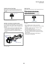
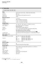
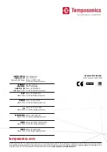
Cables
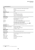
Programming tool
PUR cable
Part no. 530 052
Tefl on
®
cable
Part no. 530 112
Silicone cable
Part no. 530 113
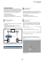
Programming kit
Part no. 254 590
Material: PUR jacket; orange
Features: Twisted pair, shielded,
highly fl exible
Cable Ø: 6.4 mm (0.25 in.)
Cross section: 3 × 2 × 0.25 mm
2
Bending radius: 5 × Ø (fixed insulation)
Operating temperature:
−30…+80 °C (−22…+176 °F)
Material: Tefl on
®
jacket; black
Features: Twisted pair, shielded, fl exible
Cable Ø: 7.6 mm (0.3 in.)
Cross section: 4 × 2 × 0.25 mm²
Bending radius: 8 – 10 × Ø
(fi xed installation)
Operating temperature:
−100…+180 °C (−148…+356 °F)
Material: Silicone jacket; red
Features: Twisted pair, shielded,
highly fl exible
Cable Ø: 7.2 mm (0.28 in.)
Cross section: 3 × 2 × 0.25 mm²
Bending radius: 5 × Ø (fi xed installation)
Operating temperature:
−50…+180 °C (−58…+356 °F)
Kit includes:
1 × interface converter box,
1 × power supply
1 × cable (60 cm) with M12 female
connector (8 pin), straight – D-sub
female connector (9 pin), straight
1 × cable (60 cm) with M16 female
connector (7 pin), straight – D-sub
female connector (9 pin), straight
1 × cable (60 cm) with 6 × terminal
clamp – D-sub female connector
(9 pin), straight
1 × USB cable
Software is available at:
www.mtssensors.com


