Chapter 1
Setting Up the CoreModule 410
4
QuickStart Guide
CoreModule 410
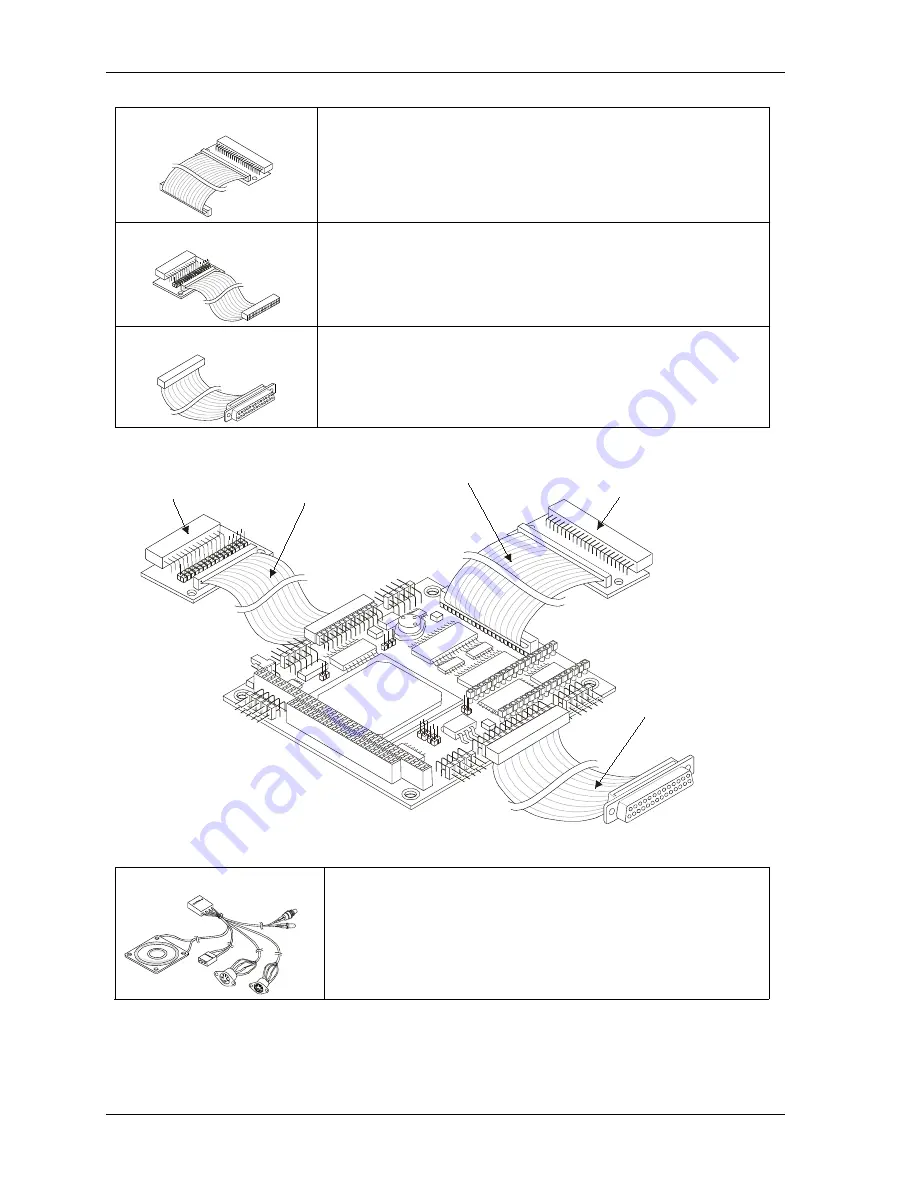
1) Connect Floppy Cable
The floppy cable and its adapter are connected to the floppy drive
connector (J8). See Figures 1-1, 1-2, and 1-3.
2) Connect IDE cable
The IDE cable and its adapter are connected to the IDE connector (J6).
See Figures 1-1, 1-2, and 1-3.
3) Connector Parallel cable
The parallel cable is connected to the parallel port (J4). See Figures
1-1, 1-2, and 1-3.
IDE Cable & Connector
Pin Adapter
(2mm to 0.1 inch)
Pin Adapter
(2mm to 0.1 inch)
Floppy Drive
Cable & Connector
Parallel Port
Cable & Connector
C
M
410
_05aa
Figure 1-3. Connecting Floppy, IDE, and Parallel Cables
4) Connect Utility cable
The Utility cable is connected to the Utility connector (J5).
See Figures 1-1, 1-2, and 1-4.
Artisan Technology Group - Quality Instrumentation ... Guaranteed | (888) 88-SOURCE | www.artisantg.com


