Chapter 2
Product Overview
CoreModule 420
Reference Manual
11
Connectors, Jumpers, and LEDs
Connector Definitions
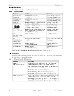
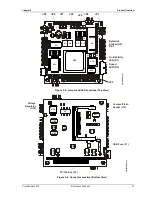
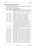
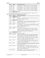
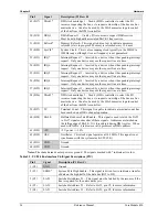
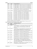
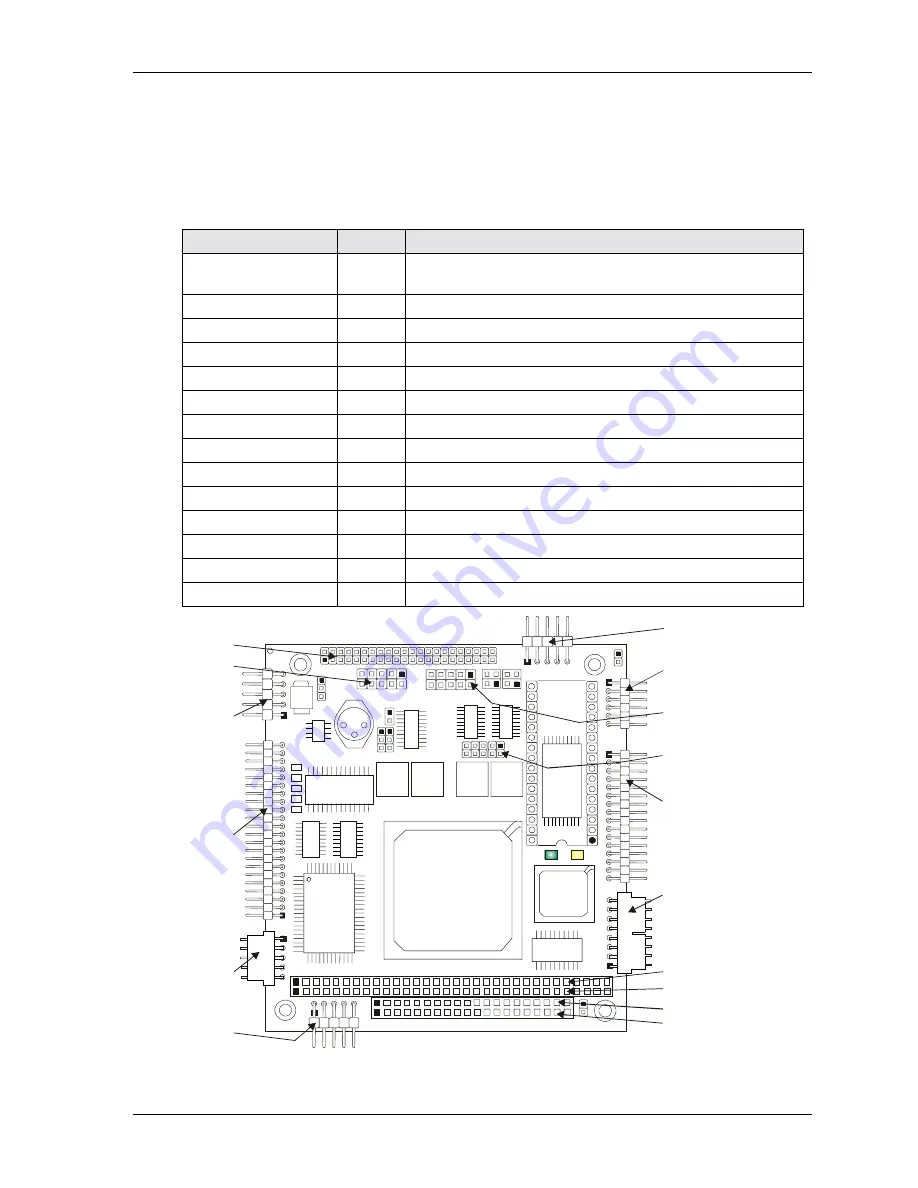
Table 2-2 describes the connectors shown in Figures 2-4 to 2-6. Refer to Appendix B for part #s.
Table 2-2. Module Connector Descriptions
Jack/Plug #
Access
Description
P1A/1B & P1C/1D –
PC/104 Bus
Top/
Bottom
104-pin connector used for PC/104 (ISA) bus
J2 – Ethernet
Top
8-pin, 0.1”, connector used for the Ethernet interface
J3 – Serial 1 (COM1)
Top
10-pin, 0.1”, connector used for the Serial 1 interface
J4 – Floppy/Parallel
Top
26-pin, 0.1”, connector provides the Floppy/Parallel interface
J5 – Utility
Top
10-pin, 0.1”, connector used for the Utility interface
J6 – IDE
Top
44-pin, 2mm connector used for the IDE interface
J7 – Power
Top
10-pin, 0.1”, connector used for the Power connection
J8 – GPIO (User)
Top
10-pin, 2mm connector used for the User defined GPIO signals
J9 – Serial 2 (COM2)
Top
10-pin, 0.1”, connector used for the Serial 2 interface
J10 – USB
Top
5-pin, 0.1”, connector used for the USB interface
J11 – Video
Top
44-pin, 2mm connector used for the LCD/CRT interface
J12 – CompactFlash
Bottom
50-pin connector used for CompactFlash cards
J13 – Serial 3 (COM3)
Top
10-pin, 0.1”, connector used for the Serial 3 interface
J14 – Serial 4 (COM4)
Top
10-pin, 0.1”, connector used for the Serial 4 interface
U5
J3
JP2
J4
U6
U15
U16
D1
D2
U14
U8
U7
U9
U10
J8
JP7
JP8
JP
9
JP6
U3
6
U3
5
U3
U4
0
U4
1
U11
L5
J2
P1
J7
J10
J11
J9
U1
2
D8
U13
J13
J14
J5
JP4
JP5
9
10
10
2
4
3
1
1
2
1
2
JP1
Serial 3 (J13)
(COM 3)
Floppy/Parallel (J4)
Serial 1 (J3)
(COM 1)
GPIO (J8)
Power (J7)
Ethernet (J2)
USB (J10)
P1D
(PC104 Bus)
IDE (J6)
Video (J11)
P1B
P1A
P1C
Serial 2 (J9)
(COM 2)
Serial 4 (J14)
(COM 4)
Utility (J5)
C
M
420R
F
M
_01b
Figure 2-4. Connector Locations (Top View)
Summary of Contents for CoreModule 420
Page 1: ...CoreModule 420 PC 104 Single Board Computer Reference Manual P N 5001692A Revision A ...
Page 6: ...Contents vi Reference Manual CoreModule 420 ...
Page 10: ...Chapter 1 About this Manual 4 Reference Manual CoreModule 420 ...
Page 22: ...Chapter 2 Product Overview 16 Reference Manual CoreModule 420 ...
Page 50: ...Chapter 3 Hardware 44 Reference Manual CoreModule 420 ...
Page 64: ...Appendix A Technical Support 58 Reference Manual CoreModule 420 ...
Page 66: ...Appendix B Connector Part Numbers 60 Reference Manual CoreModule 420 ...
Page 70: ...Index 64 Reference Manual CoreModule 420 ...
Page 71: ......
Page 72: ......


