background image

7

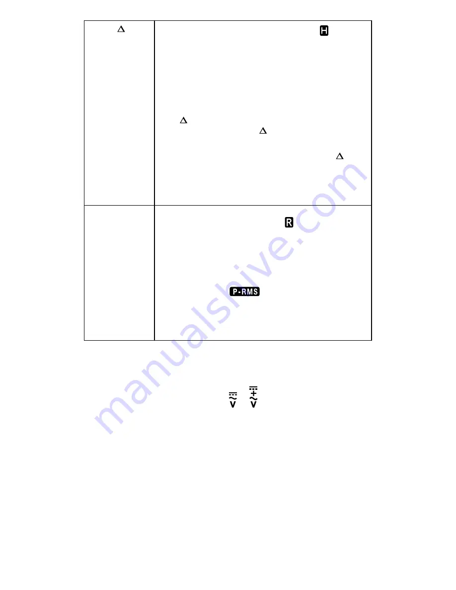
HOLD /   ZERO

Press HOLD to freeze the display reading (   is 

displayed) and releases the reading when pressed a 

second time.

W


Warning

To avoid possible electric shock or personal injury, 

when Display HOLD is activated, be aware that the 

display will not change when you apply a different 

voltage.

Press   ZERO (HOLD) > one second to clear last 
reading from the display (   is displayed) and establish 
a baseline for applicable selected functions.

DC-Zero mode for dc and ac+dc currents. Press   ZERO 
(HOLD) > one second to activate DC-Zero (display 
shows “dc_0” for one second). When nulled value is 
larger than ± 5 DC A, an acoustic warning (3 short 
beeps) will occur.

REC / PEAK-RMS

Press REC button to activate maximum, minimum and 

average reading memory mode (   MAX MIN AVG 

is displayed). The meter beeps when MAX and MIN 

reading is updated during measurement. Press REC 

button again to read the MAX, MIN and AVG reading 

in sequence. Press REC button > one second to exit 

MAX/MIN/AVG reading memory mode.
Press REC / PEAK-RMS button > one second to enter 

PEAK-RMS mode ( 

 is displayed) to capture 

inrush current or voltage RMS values (80 ms). Press a 

second time > one second to exit.
Note: Auto Power Off is automatically disabled under 

MAX/MIN/AVG and PEAKRMS modes.

Measuring AC and DC Voltage

To measure ac or dc voltage:

1. Turn the rotary function switch to   or 
2. Press SELECT button to choose measurement function: AC V, DC V, 

DC+AC V, Hz or EF(Non contact voltage detection). The display reflects 
the chosen function mode. For Model AMP-210 and AMP-220, NCV(EF) 
function is designed in an independent rotary switch position. See the 
Non-Contact Voltage Detection chapter for details.

3. Connect the black test lead to the 

COM

 terminal and the red test lead 

to the V terminal. Before connecting the probes to the measurement 
points, add any clips to the probes that are necessary.

4. Measure the voltage by touching the probes to the desired test points 

of the circuit.

5. View the reading on the display.
6. When measuring AC voltage, press SELECT button to view the 

frequency reading on the display.

Summary of Contents for AMP-210

Page 1: ...210 AMP 210 EUR 600A AC TRMS Clamp Multimeter AMP 220 AMP 220 EUR 600A AC DC TRMS Clamp Multimeter AMP 310 AMP 310 EUR 600A AC TRMS Clamp Multimeter AMP 320 AMP 320 EUR 600A AC DC TRMS Clamp Multimet...

Page 2: ......
Page 3: ...P 220 AMP 220 EUR 600A AC DC TRMS Clamp Multimeter AMP 310 AMP 310 EUR 600A AC TRMS Clamp Multimeter AMP 320 AMP 320 EUR 600A AC DC TRMS Clamp Multimeter User Manual 7 2014 6003318 A 2014 Amprobe Test...

Page 4: ...ption of the problem or the service requested and include the test leads with the meter Non warranty repair or replacement charges should be remitted in the form of a check a money order credit card w...

Page 5: ...ltage 7 Voltage detection NCV 8 Measuring AC and DC Current 9 Precise Low Current Measurement 10 Microamps A Measurement 11 Measuring Resistance Continuity and Diode 12 Measuring Capacitance and Tempe...

Page 6: ...ion AMP 210 AMP 210 EUR Series TRMS Clamp Multimeters AMP 320 TRMS CAT III 600V COM OFF NCV EF SELECT HOLD REC ZERO PEAK RMS MAX 600A 600V CAT III 1 7 8 9 2 1 1 1 4 3 5 6 11 12 10 8 Precise Low Curren...

Page 7: ...e equipment is protected by double insulation or reinforced insulation J Earth Ground CAT III Overvoltage Category lll is for equipment intended to form part of a building wiring installation Such equ...

Page 8: ...ing Read Before Using To avoid possible electric shock or personal injury Use the Meter only as specified in this manual or the protection provided by the Meter might be impaired Avoid working alone s...

Page 9: ...on test lead Disconnect circuit power and discharge all high voltage capacitors before testing resistance continuity or diodes Use only 1 5V AAA batteries properly installed in the Meter case to power...

Page 10: ...en making current measurements disconnect the test leads from the Meter Keep fingers behind Tactile Barrier Use the proper function and range for measurements Disconnect circuit power and discharge al...

Page 11: ...econd to exit MAX MIN AVG reading memory mode Press REC PEAK RMS button one second to enter PEAK RMS mode is displayed to capture inrush current or voltage RMS values 80 ms Press a second time one sec...

Page 12: ...to NCV EF EF is displayed For AMP 310 and AMP 320 turn the rotary function switch to or press SELECT button to toggle to NCV EF mode EF is displayed 2 The voltage detection antenna is located along th...

Page 13: ...e temperatures To measure AC or DC current 1 Turn the rotary function switch to or 2 Press SELECT button to choose measurement function AC A DC A DC AC A or Hz The display reflects the chosen function...

Page 14: ...ulating currents may cause the magnetic circuits of the Jaws reach hazardous excessive temperatures To measure AC or DC low current for small conductors 1 Turn the rotary function switch to or 2 Press...

Page 15: ...locate the wire between the gas burner controller and the flame sensor 2 Disconnect one of the flame sensor wires 3 Turn the rotary switch on the Meter to 4 Connect the black test lead to the COM ter...

Page 16: ...be tested Resistance measurement The resistance reading appears on the display If the circuit is open or resistance exceeds the Meter s range the display reads OL Continuity measurement If the circuit...

Page 17: ...inal 3 Turn the Meter s rotary switch to capacitance 4 Connect the probes across the capacitor to be tested When measuring be sure to note the correct polarity of the capacitor Temperature The Meter m...

Page 18: ...connection will lead to detection failure and false indication To verify signal connection and the correct rotation indication swap any of two signal connections l to check for indication of reverse m...

Page 19: ...ws Enbp When making rotary measurement if the rotary indication segments indicate a clockwise movement the beeper sounds a single long beep per segment cycle If the rotary indication segments indicate...

Page 20: ...ections Current Hz functions via jaws 600 A ac dc rms at 400Hz Voltage 3 Phase Rotation functions via terminals 660 V dc 920 V ac rms Other functions via terminals 600 V ac dc rms E M C Meets EN61326...

Page 21: ...Crest Factor 2 5 1 at full scale 5 1 at half scale or otherwise specified and with frequency spectrum not exceeding the specified frequency bandwidth for non sinusoidal waveforms DC Voltage Range Accu...

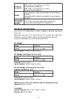
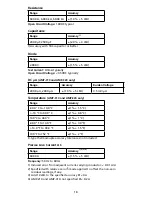
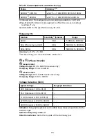
Page 22: ...5 mV A Temperature AMP 310 and AMP 320 only Range Accuracy 40 0 C to 10 0 C 1 1 5 C 10 C to 99 9 C 1 0 8 C 100 C to 400 C 1 1 C 40 0 F to 14 0 F 1 3 0 F 14 0 F to 99 9 F 1 1 5 F 100 F to 752 F 1 2 F...

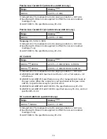
Page 23: ...5 600 0 A 1 8 5 LSD 50 Hz to 100 Hz 60 00 A 4 5 600 0 A 2 0 5 LSD 100 Hz to 400 Hz 1 Induced error from adjacent current carrying conductor 0 01 A A 2 AMP 220 and AMP 320 maximum crest factor 2 1 at f...

Page 24: ...z 60 A 600 A 40 A 50 00 Hz to 400 0 Hz Accuracy 1 0 5 LSD 1 DC bias if any not more than 50 of Sine rms 3 Phase Rotation measurement Voltage Range 65 V to 600 V sine wave only Frequency Range 35 Hz to...

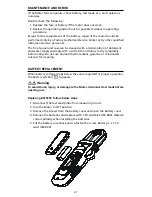
Page 25: ...y with a soft cloth and allow to dry completely before using Do not use aromatic hydrocarbons gasoline or chlorinated solvents for cleaning BATTERY REPLACEMENT When battery voltage drops below the val...

Page 26: ...nfo amprobe com Everett WA 98203 Tel 877 AMPROBE 267 7623 Amprobe Europe Beha Amprobe In den Engematten 14 79286 Glottertal Germany Tel 49 0 7684 8009 0 Visit www Amprobe com for Catalog Application n...

Reviews: