background image

3


AMPTEC


MADE IN USA


RESEARC

www.amptec.com


CAGE CODE 1CRL2 


PHONE 800-350-5105


1


4  5


OP247 Adapter


FUSE - 

2 ampere


3AG FAST BLO


RS232C


Interface 

revision 2.0


V

HI 

V

LO 

I

HI 

I

LO


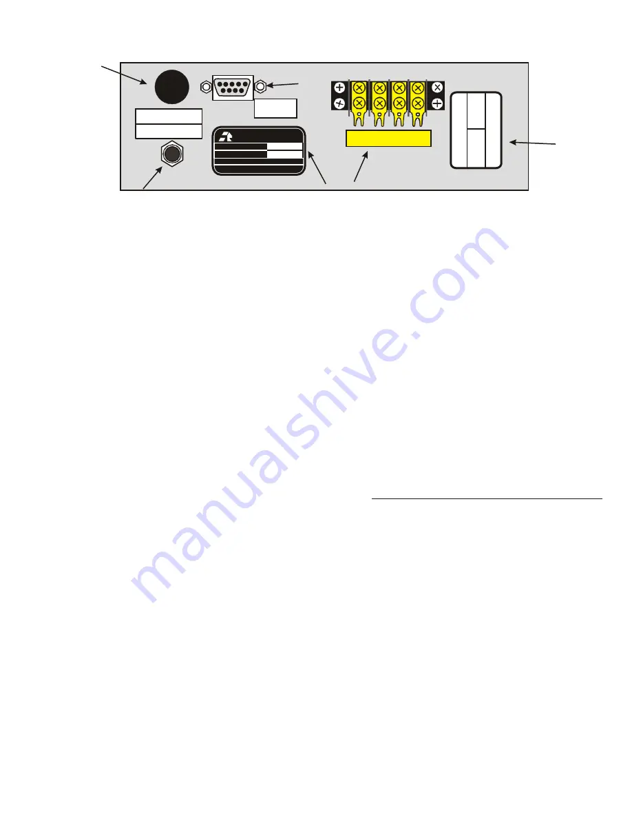
AMPTEC 620A-4 REAR PANEL configured with Option "232",  "247"


(not part of NSN 6625-01-460-1499NM package)


6


620A-4 Rear Panel with options RS232C I/O 

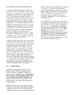
The AMPTEC 620A-4 rear panel (shown above) may 
contain many optional jacks, terminals, labels, and 
stickers. Only the option "247" Continuous Isolated 
Operating Power DC Adapter (item #1) plugs in the rear 
panel jack for isolation and to continuously operate the 
unit. 


Item 2 

is the fuse holder - replace with a 2 ampere 3 AG 

type fast blow fuse (rarely needs replacing). 


RS232C Serial Interface - Item # 3 is the safety isolated 
RS232C serial I/O (9 pin D type Sub-min connector). 
This RS232C Interface provides the meter’s resistance 
measurements to a PLC fitted with a serial port. The 

RS232C protocol settings should be 9600 Baud, 8 
Bits, No parity, 1 Stop Bit, 
9 pin D Sub-min 
connection
.  
 
RS232C Command Set (Option 232) 

(NOTE: All front panel range buttons must be de- 
selected (press in halfway) 

with all range pushbuttons 

out 

to disable with local lockout and enable RS232C 

control. 

Note commands are case sensitive


C       Continuous Read Mode - RS232C I/O 

outputs a 

data string  every A to  D conversion  cycle, approx

2.5 

times per second. 


Single Read Mode - RS232C I/O 

outputs a 

single data string upon reception of a “R” command. 


Read - 

Commands 

RS232C I/O 

to output a 

single data string (1 resistance reading). 


r

De-Selects all Ranges 

r1 

Selects the 20 Ohm Range 

r2 

Selects the 200 Ohm Range 

r3 

Selects the 2K Ohm Range 

r4 

Selects the 20K Ohm Range 

Version 

c

ommands board to output the firmware 

version string. 

Data Format - 

The 

RS232C I/O 

outputs a data 

string with the following format: 


1.2345E+3 The measurement is always in Ohms 

(where E+3 = 10

+3

scientific notation style) 

. The 

Exponent is defined below. 

1.2345E+3 = 1.2345 

KOhms 

(where E

+3

=10

+3

). 

1.3700E+1 

13.700 

Ohms 

(where E

+1

=10

+1

Range 

Exponent 


20.0 

Ohm 

E+1 

200.0   Ohm 

E+2 

2.0 K   Ohm 

E+3 

20  K   Ohm 

E+4 


An overrange condition is indicated by 
9.9999E

nn..

Where nn is the selected resistance 

range exponent. A Range Error is indicated by 
x.xxxxERR. 


Item # 4 

is the unit’s serial number sticker. 


Item # 5 

is the gold plated 4 terminal rear terminal 

strip (they are wired in parallel with the front termi- 

nals). If a “2 wire ohms” connection is made then 
the 

high and 

high terminals should be shorted 

together, and the 

low and 

low terminals should 

be shorted. The AMPTEC 620A-4 Voltage High, 
Voltage low, Current high and Current low wires 
are permanently connected to the gold plated rear 
terminal strip ( seel labeled gold plated terminal 
strip on rear panel). 


Item #6 Calibration Sticker - 

If the calibration 

due date has expired (1 year) AMPTEC or a Cal. 
Lab can contact to re-certify the AMPTEC 620A-4 
Explosive Safety Ohmmeter/Igniter Tester. contact 
AMPTEC customer service 001-512-858- 4045. 

A

M

P

TE

C

 6

2

0

A

4


S

e

ria

#

 620A

4

-1

2

7

8


D

A

T

E


CA


TED


D

A

T

E

 D

U

E


L

IB

R

A


2

3

J

U

N

E2

0

0

4

 2

3

J

U

N

E2

0

0

5


C

E

R

TI

F

IED

 B

Y


D

W

H


MODEL NUMBER


620A4


SERIAL NUMBER


620A4-1278


Summary of Contents for 620A-4

Page 1: ...MODEL 620A 4 OPERATION MAINTENANCE MANUAL Phone 1 512 858 4045 Fax 1 512 858 4340 www amptec com info amptec com REV H ...

Page 2: ... and Safety Board Approvals SECTION B IGNITERTESTER FAILSAFE OHMMETER SPECIFICATIONS Table B 2 Specifications SECTION C OPTIONAL ITEMS AND ACCESSORIES C 1 Available Accessories and Options C 2 Test Lead and Probe Sets SECTION D OPERATION AND USE D 1 General D 2 Front Panel D 3 Rear Panel D 4 4 Wire Resistance Measurement D 5 Connections D 6 Failsafe Operation D 7 Battery Monitoring Circuitry Figur...

Page 3: ...onverter E 4 1 Reference Voltage E 4 2 LED Display E 5 Ohms to DC Converter E 5 1 Constant Current Source E 5 2 Constant Current Circuit Operation E 6 Failsafe Design E 7 Ultra Safe Power Supply Scheme E 8 Relay Board General Operation SECTION F ROUTINE MAINTENANCE F 1 General F 2 Required Test Equipment F 3 Calibration Procedure F 4 Battery Replacement Instructions ...

Page 4: ...EARCH ensures that test current levels do not exceed the specified failsafe current in a worst case component failure situation The failsafe feature is tested in every instrument before shipment Should the rechargeable batteries reach a low charge level a minus sign will appear on the display The 620A 4 has a battery monitoring circuit that indicates when to charge the batteries A 2 Receiving Unpa...

Page 5: ... the 620A 4 requires twice as much time to fully recharge as the amount of discharge time For example if the instrument was used continuously for 2 hours the AC adapter must be connected for 4 hours to fully restore the charge 620A 4 rear panel charging jack is electrically disconnected from all 620A 4 circuitry A fully charged battery pack typically powers the 620A 4 for approximately 8 hours bef...

Page 6: ...nment does not exceed the specifications of Table B 2 You may also have a test procedure or technical order T O that has you inspect the calibration sticker on the AMPTEC 620A 4 Igniter Tester to determine that it is still valid or within its calibration interval Avoid exposing the 620A 4 to extreme temperatures hot or cold which will affect accuracy and shorten battery lifespan A 5 Serial Number ...

Page 7: ...ohm range is 5mA when operating normal 8mA worst case when faulty Instrument Display 20 000 count 4 digit Super Bright Light Emitting Diodes LED Over Range Indication select next higher range 620A 4 Display flashes Measurement Update Rate Approximately 300ms Voltage Protection Maximum Input 250VDC or ACpeak without damage Open Circuit Current Source Compliance Voltage clamped at 1 6 volts Power 4 ...

Page 8: ... etc Test Leads and Probes All AMPTEC Igniter Tester Leads and Probe sets are a minimum 48 length call the Sales Department for any custom requirement Option 620RACK Rack Mount Adapter Option 620RACK includes an adapter tray that allows any single AMPTEC 620 series tester to be flush panel mount installed in a standard 19 equipment rack C 2 Test Lead Sets and Probes Option 290 Alligator Clip Lead ...

Page 9: ...urfaces and parts i e flares that alligator clip can t reach Option 430 4000 ITS Mating Connector AMPTEC offers an adapter connector that provides equivalent circular socket connections J9 Connector found on SIMPSON 4000 ITStm and Alinco 101 series Circuit Igniter Testers In some applications i e AIM 7 Missile harnesses regular alligator clip leads cannot properly connect to screw on ring collar t...

Page 10: ...re manually selected by pressing the desired range switch on the front panel The range select pushbutton for the lowest resistance range 20 Ohms left most resistance range button indicated above the range select buttons When a given range is selected pushed in the other range switches pop out and inform the user It is obvious to the 620A 4 user which resistance range has been selected as it is pus...

Page 11: ...ommands RS232C I O to output a single data string 1 resistance reading r0 De Selects all Ranges r1 Selects the 20 Ohm Range r2 Selects the 200 Ohm Range r3 Selects the 2K Ohm Range r4 Selects the 20K Ohm Range V Version commands board to output the firmware version string Data Format The RS232C I O outputs a data string with the following format 1 2345E 3 The measurement is always in Ohms where E ...

Page 12: ...r sources The internal current source inherently overcomes all series resistance within compliance voltage limits and delivers a precise constant current The internal high impedance DVM senses the voltage drop across the load There is negligible contact and lead resistance error created by the voltage measurement because the high input impedance of the DVM limits current flow in the voltage leads ...

Page 13: ...Series Igniter Tester Ohmmeter incorporate a proprietary current source design that renders them incapable of delivering excessive voltage or current to the device under test The typical fail safe current for each range is indicated under the corresponding range switch on the 620A 4 front panel Please refer to section 5 6 for a technical description of the failsafe circuitry Every 620A 4 Series Fa...

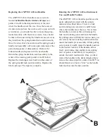
Page 14: ...to the center of the spring loaded lock notch assembly Replace the black end caps The repair is complete Rotating the AMPTEC 620A 4 Instrument Case and Handle Position The AMPTEC 620A 4 handles position can be easily adjusted or rotated with the simple maneuver described below There is a lock notch rotating joint at points A and B below where the handles meet the case Never force the handles to ro...

Page 15: ...cate the batteries need charging or fuse needs replacing If the 620A 4 exhibits problems that cannot be eliminated by reviewing Chapters B and D the following guidelines have been established to help solve the problem E 2 1 Localizing the Problem Chapter D 2 discusses how to use the Functional Test Section of the 620A 4 Tester to help localize the problem The key to successful troubleshooting is t...

Page 16: ...or move the replacement part until the solder has cooled Cold solder and bad solder joints can cause more problems Use the chassis ground connect to the common terminal of the functional test section connection i e connect to an earth ground to avoid a static discharge to a static sensitive component Handle all 620A 4 internal components as if they are static sensitive if you are not sure See Next...

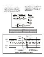
Page 17: ...t the back of this manual In the following descriptions references to integrated circuits are given in the form IC201 1 which refers to Integrated Circuit 201 pin 1 E 4 Analog to Digital Conversion The A to D conversion is done with a ICL8068 ICL71C03 chip set The ICL8068 takes care of the analog part and the ICL71C03 takes care of the digital part of the 4 digit 20 000 count dual slope conversion...

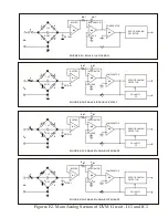
Page 18: ...ING DETECTOR COMPARATOR _ A3 INTEGRATOR _ A2 CAZ BUFFER _ A1 1 µF 4 2 5 RINT CINT FIGURE E 2D PHASE lll AND DE INTEGRATE POLARITY FF 3 CSTRAY CREF 6 1 VIN ZERO CROSSING DETECTOR COMPARATOR _ A3 INTEGRATOR _ A2 CAZ BUFFER _ A1 1 µF 4 2 5 RINT CINT Figures E2 Main Analog Section of DVM Circuit IC1 and IC2 3 FIGURE E 2A PHASE l AUTO ZERO 6 1 VIN CSTRAY CREF ZERO CROSSING DETECTOR COMPARATOR _ A3 INTE...

Page 19: ...ished in Phase I The time or number of counts required to do this is proportional to the input voltage E 4 1 Reference Voltage The precision reference voltage required to do the A D conversion is developed by IC201 The zener voltage is attenuated to approximately 0 5V This voltage is applied to IC2 7 E 4 2 LED Display The output format from IC2 is in Binary Coded Decimal BCD format Each digit is s...

Page 20: ...st as it was when the output terminals were shorted The current through RL is 10 milliamperes just as it was through the jumper when the output terminals were shorted E 6 Failsafe Design Reference to the AMPTEC 620A 4 Tester Igniter Tester schematic will show that the output of IC202 6 is applied to the base of transistor Q202 which acts as a current limiter The worst case component failure that c...

Page 21: ...e Power Supply Scheme The 5 volt power supply is provided directly by the batteries for driving the LED displays and digital logic The 5VD is used for driving IC8 the low battery detection circuit The 15V power supply is generated by IC7 for the digital voltmeter DVM chip set IC1 and IC2 The 5 VA is developed by one DC to DC convertor circuitry composed of Q103 Q104 T102 D103 D104 IC102 for the ne...

Page 22: ...the main board IC 1 is a ribbon cable header that goes to the top panel and connects to the range push buttons covered by silicone rubber boots and their corresponding panel mount LEDS IC 2 is a latch that will latch its output to the corresponding range push button input Its output turns on the front panel LED acts as a range mode indicator LED and a corresponding relay that connects to the main ...

Page 23: ...other than the AMPTEC 620A 4 use the same basic procedure however different standard resistor values may apply for different resistance ranges Precision Resistors 0 1 ohm 0 01 Accuracy 10 ohms 0 005 Accuracy 100 ohms 0 005 Accuracy 1000 ohms 0 005 Accuracy 10000 ohms 0 005 Accuracy Test Leads 4 wire lead set AMPTEC Option 300 or 301C F 3 Calibration Procedure The 620A 4 should be calibrated with f...

Page 24: ...feet screws taking care not to pinch any wires Low Battery Indicator The variable potentiometer trimpot RV3 is factory adjusted to have the low battery indicator come on at 4 50 VDC To make this adjustment remove the fuse from the fuse holder With an adjustable DC power supply set the power supply output to be 4 50 VDC Be sure to observe power supply polarity Connect the power supply to the test p...

Reviews: