620LK Operation and Maintenance Manual – Rev. J – Updated January 2020
Page 15
13231 Rooster Springs Rd.
Austin, TX 78737
T:
(512) 858-4045
E:
info@amptec.com
amptec.com
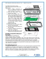
E-6.1 Current Source PCB Diagnostic Test Routine
The following steps can help determine if the current source circuitry is faulty:
1) Put output leads across a 0.100
Ω resistance standard (
0.005% or better).
2) Measure the voltage drop with a DC Voltmeter. It should be 0.0100V.
If the above test proves untrue, then the current source circuitry is possibly faulty, and
may need replacing. See section E-2 on page 13 for more information about sending
your product in for repair.
E-6.2 Digital Voltmeter (DVM) PCB Test Routine
The following steps can help determine if the DVM circuitry is faulty:
1) Short the output leads.
2) Check for a reading of 0.000.
3) Put the output leads across a 0.100
Ω resistance standard.
4)
The display should read 100.00 mΩ
(± 10 counts depending on the resistor’s
accuracy).
If the above test proves untrue, then the DVM circuitry is possibly faulty, and may need
replacing. See section E-2 on page 13 for more information about sending your product
in for repair.
E-7 620LK Calibration Procedure
The 620LK’s rear panel calibration sticker must be removed to access the two
adjustment potentiometers located on the DVM PCB.
Please note that if the tamper-
proof calibration sticker is removed, this voids the product’s calibration and
warranty.
All the meter’s calibration adjustments (via trimpots) are accessed through two holes
located in the upper right area of the rear panel, under the tamper-proof calibration
sticker. The two holes (see diagram below) are for zero and full-scale adjustments. A
set of two hole plugs normally cover the zero and full-scale adjustment holes.


