AS5145B Eval-Kit Stepper Motor
www.ams.com
Revision 1.1 / 01/23/14
page 3/9
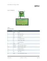
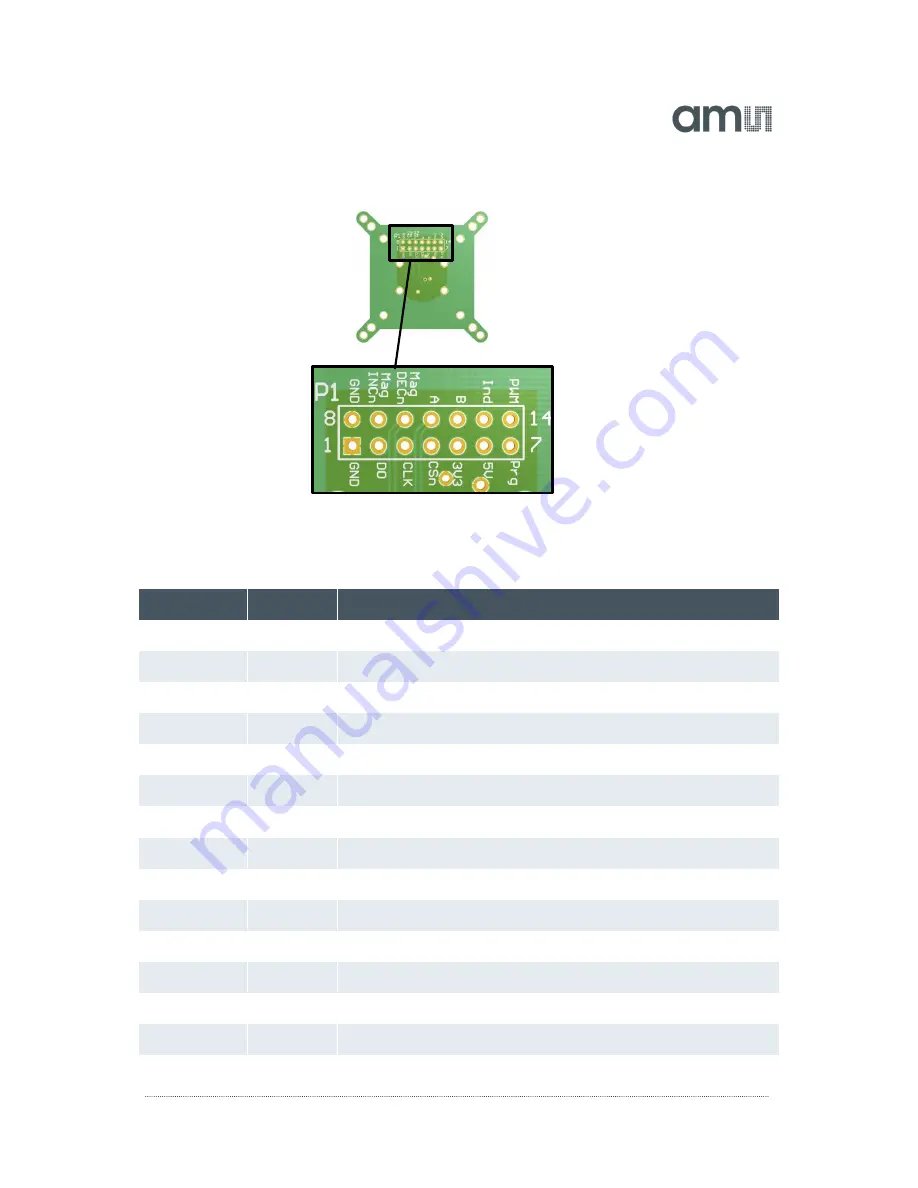
Figure 1:
Connector
Table 1:
Connector pinout
Pin
Description
Info
1
GND
Ground
2
DO
Data Output of SSI
3
CLK
Clock Input of SSI
4
CSn
Chip Select
5
3V3
3.3V-Regulator Output.
6
5V
Positive Supply Voltage.
7
Prg
Programming Input.
8
GND
GND
9
MagINCn
magnet field status indicator
10
MagDECn
magnet field status indicator
11
A
Quadrature Output A
12
B
Quadrature Output B
13
Ind
Index Output
14
PWM
Pulse Width Modulation output


