AS5601 Adapter Board
ams Eval Kit Manual, Confidential
Page 9
[v1-00] 2014-Jul-31
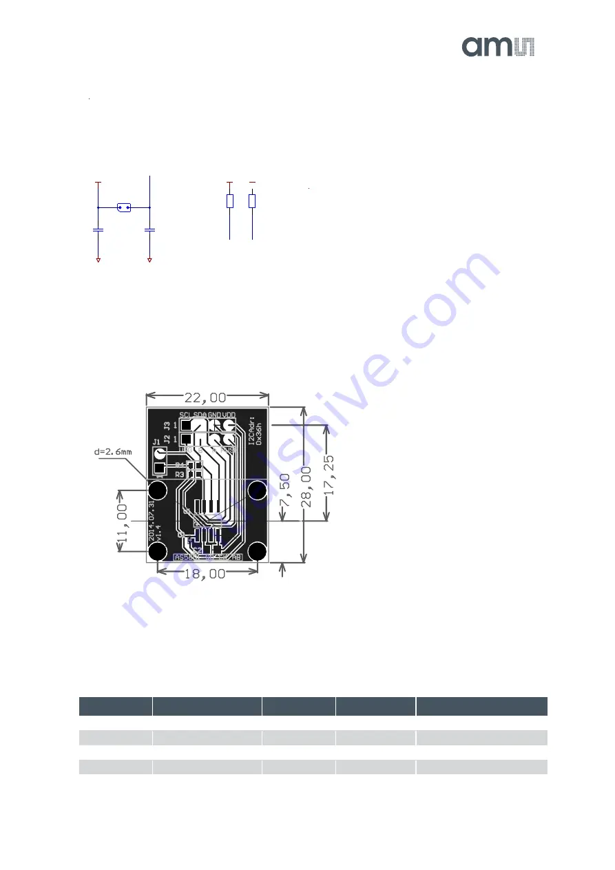
7.2 Layout and Board Dimensions
The PCB layout is shown below in
Figure 7:
Adapterboard layout
7.3 Bill of Materials
The BOM of the pcb is below in
Table 3:
Bill of Materials
Designator
Part
Footprint
Manufacturer
Comment
J1
Jumper
J2
Header
J3
Header
C1
C0603
0603
1
1
2
2
3
3
4
4
D
D
C
C
B
B
A
A
Size
Date
Project Title
Revision
Sheet
of
Originator RPH
AS5601-AB-1.4
A4
1
29.01.2014
3
3
1
2
3
4
not populated
Stiftleiste4_THMD
J3
1
2
3
4
Stiftleiste4_THMD
J2
not populated
VDD
VDD
GND
SDA
SCL
GND
VREG
PUSH
B
A
A
B
10uF
Farnell
1833804
C2
C0805
100nF
Farnell
1740614
C1
C0603
GND
VDD
GND
V
R
E
G
J1
not populated
R3
NC
Note1: Supply
J1=OPEN: 5V
J1=CLOSED: 3.3V
Note2: Optional pull-ups
Note3:
Adapterboard can be used with AS5XXX-UCB-1.0
Note4:
AS5601 I2C Address is 0x36h
(Use 4pin I2C header in 3.3V mode)
VREG
A2
PUSH
A3
GND
A4
I2CLK
B2
I2CD
B3
B
B4
VDD
A1
A
B1
AS5601
U1
AS5601
R4
NC
S
C
L
S
D
A
VDD
VDD
1
1
2
2
3
3
4
4
D
D
C
C
B
B
A
A
Size
Date
Project Title
Revision
Sheet
of
Originator RPH
AS5601-AB-1.4
A4
1
29.01.2014
3
3
1
2
3
4
not populated
Stiftleiste4_THMD
J3
1
2
3
4
Stiftleiste4_THMD
J2
not populated
VDD
VDD
GND
SDA
SCL
GND
VREG
PUSH
B
A
A
B
10uF
Farnell
1833804
C2
C0805
100nF
Farnell
1740614
C1
C0603
GND
VDD
GND
V
R
E
G
J1
not populated
R3
NC
Note1: Supply
J1=OPEN: 5V
J1=CLOSED: 3.3V
Note2: Optional pull-ups
Note3:
Adapterboard can be used with AS5XXX-UCB-1.0
Note4:
AS5601 I2C Address is 0x36h
(Use 4pin I2C header in 3.3V mode)
VREG
A2
PUSH
A3
GND
A4
I2CLK
B2
I2CD
B3
B
B4
VDD
A1
A
B1
AS5601
U1
AS5601
R4
NC
S
C
L
S
D
A
VDD
VDD


