background image

11 


AM-TC10626LA


4.


Operation


NOTE


Do  not  operate  the  machine  before  having  completed  training  and  qualified  for  operating  the  tire 

changer.  Use  appropriate  equipment,  tools,  and  personal  protective  equipment,  such  as  eyeglasses, 

earplugs, and work boots

.


When operating the tire changer. Make sure that the power, air sources, and the oil level in the oil cup 

are by the requirements

.


4.1. 

Principles 


For easier demounting and better protection of the tire and rim, lubricate the area between the rim and tire 

bead, where the bead breaker shoe goes in, with industrial lubricant or thick soap solution.


Pay special attention to the rotary direction marked on some flanges or tires.


Fit the tire on the rim of matched size.


Check  for  damages  (distortions,  surface  damages,  excessive  runout,  erosion,  or  overall  wear)  before 

demounting.


Never ignore the mounting and demounting requirements of the special wheel.


When inflating  the tire,  make  sure the  pressure increases in  an even  way. 

Check the rim  as often  as 

possible.


Fig 11 


Fig.12 

4.2. 

Demounting Tire 

Preparing 

Deflate the tire thoroughly. 

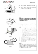
Remove all the foreign substance and weights 

from the rim

as fig.11

Demounting 
 

NOTE


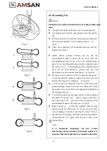
Lubricate  the  bead  with  a  brush  with  lubricant 

before the shoe touches the bead.  Otherwise, the 

tire bead will be worn

as fig.12


Summary of Contents for AM-TC10626LA

Page 1: ...PLEASE READ THE PRODUCT MANUAL ENTIRELY BEFORE INSTALLING OR OPERATING THE LIFT ...

Page 2: ...ed in this manual The machine should be installed in a place close to the main power source and compressed air system Install the machine on the smooth concrete ground or other ground with hard flooring 4 sets of anchor bolts can be used to fasten the machine onto the ground to avoid vibration and noise Leave enough space for the operation and maintenance of the machine The space should be no less...

Page 3: ... 2 Demounting Tire 11 4 3 Mounting Tire 14 4 4 Inflating Tire 15 5 Trouble Shooting 15 6 Maintenance 16 7 Storing and Scrapping 16 7 1 Storing 16 7 2 Scrapping 16 8 Spare Parts List 17 9 Exploded Drawings 21 9 1 Column Assembly 21 9 2 Turntable Assembly 22 9 3 Gearbox Motor Assembly 23 9 4 Body Assembly 24 9 5 Bead Breaker Cylinder Breaker Arm Assembly 25 9 6 Quick inflating system optional 26 9 7...

Page 4: ...the operating personnel The distance of the bead breaker is large enough for a big tire The tire lever and lubrication box are easy to reach 1 3 Specifications Dimensions Maximum height 1900 mm Length 900 mm Width 850 mm Noise Working noise 70dB A Air supply Working pressure 8 10 bar Bead breaker maximal work force 14000 N 1 4 Applicable Range Electric specifications Voltage to choose from NO Volt...

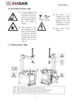
Page 5: ... to keep hands and other body parts away when fastening the mount demount head or when the turntable is running Caution should be taken when separating the tyre from rim The bead breaker shoe will move rapidly and forcefully when the pedal is depressed Keep body and materials away from the work area Please change the safety signs if it gets blurred or lost When one or more safety signs get lost do...

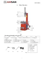
Page 6: ...E Bead breaker shovel H Mount demount head L Clamping jaw B Bead breaker pedal F Bead breaker arm I Swingarm M Slide C Jaw open pedal G Rubber buffer J Adjusting handle N Turntable D Jaw close pedal K Locking lever O Clamping cylinder Fig 2 Accessories provided are shown in Fig 2 001 Inflating gun Inflator tube Tire lever Jaw protector ...

Page 7: ...attract dust Clean it when necessary 3 2 Location The place to install the machine should be by safety regulations The machine should be installed in a place close to the main power source and compressed air system Install the machine on the smooth concrete ground or other ground with hard flooring 4 sets of anchor bolts can be used to fasten the machine onto the ground to avoid vibration and nois...

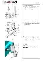
Page 8: ...on keep column vertical prevent it from tilting avoid injury 3 3 2 Vertical column installation Install vertical column G into column hole on the swing arm H from downside to upside lock vertical column with lock lever L note Care about mounting head installation direction Place a rim on t h e turntable for reference then install return spring I knob J fasten connecting screw K as fig 5 c NOTE Whe...

Page 9: ...reaker arm assembly installation Step 1 Arm installation As fig 6 a put arm M into fixed seat N tighten with hex bolt O and flat washer P Step 2 Arm spring installation As fig 6 b hang one end of spring S into the hole R use spring hook U hook another end of spring S to spring pin T take out spring hook U When arm installation take care avoid hands injured ...

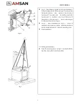
Page 10: ...er location pin V is installed note Insert Piston rod W through hole of location pin V Fasten connecting nut X when arm M lay back as fig 6 c Step 4 shovel installation As fig 6 c shovel Z installation from inside to outside install into the hole of arm M install flat washer Y fasten X connecting screw Finish installation 3 3 5 Lifting and installation Take off screws by spanner as Fig 7 Use hoist...

Page 11: ...diagram included in the User s manual Otherwise the manufacturer will not be responsible for any accidents Operation test After power is connected press pedals A Fig 9 the turntable will turn clockwise This test is very important FRL Filter Regulator Lubricator Assembly optional See Fig 10 1 Lubricator 2 Filter 3 Regulator Adjust pressure There is a button for regulator 3 When pulled up the pressu...

Page 12: ... with industrial lubricant or thick soap solution Pay special attention to the rotary direction marked on some flanges or tires Fit the tire on the rim of matched size Check for damages distortions surface damages excessive runout erosion or overall wear before demounting Never ignore the mounting and demounting requirements of the special wheel When inflating the tire make sure the pressure incre...

Page 13: ...e rim externally fig 14 NOTE Different types of clamping can be chosen by different rims In case of inside clamping fig 15 a depress pedal D shrink the jaws together place the wheel on the turntable and depress pedal C to clamp In case of outside clamping fig 15 b enlarge the jaws outward 2 3cm away from the edge of the rim place the wheel on the turntable press the rim close to the jaws depress p...

Page 14: ... slip off to avoid this before turning clockwise of the turntable may turn anti clockwise a little to make the turntable back 1 2mm If the demounting process is prevented stop the turntable from turning around lift pedal A fig 19 let the turntable turn anti clockwise If there is a tube in the tire remove it Lift wheel make the bottom edge of wheel as fig 20 Press pedal A until the bottom edge of t...

Page 15: ...e central part of the tire Depress the pedal L to turn the turntable clockwise making the lower tire bead fall into the rim groove completely as fig 23 A If a tube needs to be installed in the tire check first for the possible damages Round it onto the rim Make sure to keep the air inlet valve on the tube in the right position throughout the mounting process To install the upper tire bead place th...

Page 16: ...eumatic system 3 The pressure reducer is closed or badly adjusted for versions with this device 1 Connect the pneumatic supply 2 Correct the supply pressure 3 Open or correctly adjust the pressure reducer Other malfunctions should be checked and fixed by Professionally Qualified Personnel 4 4 Inflating Tire Danger Inflating can be highly dangerous Take precautions and pay close attention to the pr...

Page 17: ...the moving parts clean and lubricate clean with diesel as Fig 26 Keep the swing arm clean and lubricate it periodically so that it can move expectably Check the oil level in the sprayer regularly If the oil level does not reach the second line fill SAE20 Fig 27 Clear away the condensed material in the water separator around the sprayer regularly Regularly check and adjust the tension of the belt C...

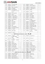
Page 18: ...29 6000134 Washer Φ10 8 112 6000296 Hex screw M8 45 1 130 6000143 Lock nut M10 4 113 6000139 Washer Φ8 1 150 2004501 Complete mounting head 1 114 6000143 Lock nut M10 1 151 2004601 Mounting head 1 115 6000134 Washer Φ10 1 152 2004701 Contact roller 1 116 2065573 Locking plate 1 153 2004801 Contact roller screw 1 117 6000187 Hex screw M10 55 1 154 6000225 Hex nut M10 16 2 118 3000501 Locking block ...

Page 19: ...05 2 310 2009201 Upper cover 1 324 2009601 Worm screw 1 311 6000166 Bearing 6010 1 325 6000337 Key 6 6 20 1 312 2009401 Gearbox shaft 1 326 3005127 Seal 25 40 8 1 313 6000102 Screw M8x20 1 327 6000170 Key 12 8 50 1 314 6000199 Washer 8 1 328 6000112 Screw M6 12 1 315 2037201 Flat washer Φ8 1 329 6000101 Key 12 8 40 1 316 2009701 pulley 1 330 6000204 Pin Φ8 16 1 317 2009501 Worm gear 1 331 6000200 ...

Page 20: ...lat washer 10 22 2 2 543 4001001 Oil mist 1 521 2009901 U support 1 544 3005074 L union IPL6 01 1 522 2010601 Short pedal 3 545 3005026 Cooper Coupling F L R 1 523 2010301 L support 1 2065790 Parts of bead breaker cylinder Fig 38 600 2065792 Complete bead breaker cylinder 1 607 3004301 O seal 20 2 4 1 601 2011201 Bead breaker cylinder 1 608 2011501 Piston rod 1 602C 602 1 602 4 Complete exhaust va...

Page 21: ...8 Screw M8 25 4 F702 6000134 Washer 10 22 2 4 F717 2064204 Support 2 F703 3003201 Valve cover 1 F718 2064221 Pin for main arm 1 F704 4000301 Rise fall control valve 1 F719 2064213 Complete cylinder 1 F705 6000344 Screw M16 30 2 F720 2064219 Connecting plate 2 F706 2064210 Main arm 1 F721 2039601 Cylinder cover 2 F707 2064205 Secondary arm 1 F722 2064220 Screw 4 F708 2037401 Washer 38 10 4 1 F723 2...

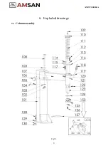
Page 22: ...Fig 34 21 AM TC10626LA 9 1 Column assembly 9 Exploded drawings ...

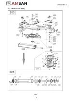
Page 23: ...Fig 35 22 AM TC10626LA 9 2 Turntable assembly ...

Page 24: ...Fig 36 22 AM TC10626LA 9 3 Gearbox motor assembly ...

Page 25: ...24 AM TC10626LA 9 4 Body assembly Fig 37 ...

Page 26: ...25 AM TC10626LA 9 5 Bead Breaker Cylinder Breaker Arm Assembly Fig 38 ...

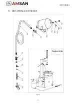
Page 27: ...26 AM TC10626LA 9 6 Quick inflating system Optional Fig 39 ...

Page 28: ...27 AM TC10626LA 9 7 Simple left help arm Optional Fig 40 INSTALL ...

Page 29: ...26LA Structure Fig 1 The main operating parts are shown in Fig 1 No Item No Item No Item A Base D Arm G Adjustable rod B Cylinder E Extended arm H Tire pressing head C Up down switch F Locking rod I Centering cone ...

Page 30: ...own on the packing list are included If any parts are missing or broken please call the manufacturer or the dealer as soon as possible Please keep the package out of children s reach 2 Location size Fig 3 Leave enough space for the operation and maintenance of this arm Keep no less than 500MM distance around for operation area 3 Installation Fix base B onto the left side of post A with 4 pieces sc...

Page 31: ... box together with the arm Tidy air tube in the frame put on the side cover 5 Testing This arm device must connect with an air compressor and the air pressure from 8 bar to 10 bar is desirable After the air is connected pull the up down switch double check if all parts on the arm working well Make sure the cylinder works upward and downward by an up down switch NOTE Please change the safety signs ...

Page 32: ...t position pull switch B down to loose rod and let centering cone going to the middle of the rim pull up switch B to lock rod Pull down switch A and let rim down as Fig 9 again press pedal F to make rim clamped by the four jaws NOTE We Suggest clamping rim from outside not clamping rim from inside if locking rim inside damage or danger may occur such as tire falling rim damaged 2 Demounting the ti...

Page 33: ...the rim Move away swing arm take down the tire from tire changer machine demounting finished NOTE Keep hands and the rest of the human body away from the moving parts of the machine Never wear a necklace bracelet or loose clothes when operating the machine as it may cause danger 3 Mounting Tire NOTE Check the size of the tire and rim to see if they match each other Fig 13 3 1 Mounting bottom bead ...

Page 34: ...ommended to mount low profile and run flat wheels As Fig 16 the arrow sign show these parts can be installed onto the mount demount head Washer on the mount demount head should be replaced when this optional lever is used Pull back the pressing roller D to the position as Fig 15 pull down switch A and let the pressing roller press tire bead into the groove the roller I on the optional lever also h...

Page 35: ...rms Optional Double arm optional 1 Structure NO ITEM NO ITEM NO ITEM 1 Back Arm 6 Screw 11 Screw 2 Pressing roller 7 Cylinder 12 Up down switch 3 Valve 8 Screw 13 Valve 4 Front arm 9 Pressing roller 14 Support shelf 5 Screw 10 Right help arm ...

Page 36: ...ation Fig 6 d As Fig 6 d open the package install D onto the post with screw E fasten it install A onto B with screw C fasten it make sure each part is working well if not adjust the gap by fastening or loose the screws Fig 8 a ...

Page 37: ...to open the jaws till big enough for rim clamping Put the tire on the turntable depress the corresponding pedal to close the jaws for clamping the tire NOTE We Suggest clamping rim from outside not clamping rim from inside if locking rim inside damage or danger may occur such as tire falling rim damaged 2 Demounting the tire 1 Clamp the rim tightly on the table lose the tire as Fig 9 when it is ne...

Page 38: ...g area Depress pedal Z to rotate turntable demount upper tire bead with the help mount demount head Pay attention t o the position where the lever inserts into Fig 10 Fig 11 3 Demount bottom tire bead For big tires hook on the left arm could be used to lift tire bead from inside pull switch upward to lift tire on the opposite side insert lever straight end to lift tire as Fig 12 make sure the leve...

Page 39: ...brasion for tire bead As Fig 13 NOTE Rim cannot be pressed by pressing head and roller during operating it is very dangerous Press pedal Z to turn the turntable together with tire pressing head mount upper bead with the help of mounting head as Fig 13 NOTE Stop operation if stuck occurred to protect the tire lift pedal Z the turntable will go backward Adjust pressing roller and pressing head opera...

Page 40: ... occurred after a long time turning fasten screw 11 4 cylinder not powerful Cylinder leakage Replace cylinder or seals 5 Valve 3 13 leakage Seals inside are broken replace the valve NOTE To keep this arm device in good condition and to prolong the work life it is necessary to do regular maintenance according to the instructions on the user s manual Ask dealers or manufacturers for help if any ques...

Page 41: ...40 AM TC10626LA Appendix 1 Electrical Diagram Fig 40 Fig 41 ...

Page 42: ...mbly 2 Inflation gun 4 Bead breaker cylinder 6 Locking cylinder Appendix 3 Fig 43 Optional accessory Fig 44 Mounting head for alloy rim Fig 43 Optional These are special plastic protectors designed for use light alloy rims Motorcycle adaptor Fig 44 Optional It can demount and mount 8 24 motorcycle tire 4 pcs set ...

Page 43: ...42 AM TC10626LA Appendix 4 MAINTENANCE LOG ...

Reviews: