14
AM-TC10626LA
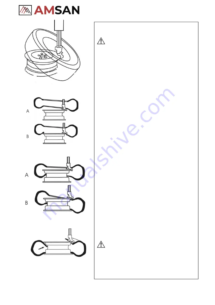
Fig.21
Fig.22
Fig.23
Fig.24
4.3.
Mounting Tire
NOTE
:
Check the size of the tire and rim to see if they match each
other
⚫
Clamp the rim tightly in the same way as demounting tire.
⚫
Use lubricant such as thick soap solution on the tire and the
rim.
⚫
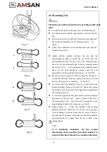
Put the bead on the rim with the left side upward, pull back
the swing arm and place it in its working position.
(
as
fig.21
)
.
⚫
Check the coordination of mount/demount head and rim.
Readjust if necessary.
⚫
Adjust relative position between the tire and the
mount/demount head to make the tire bead cross the
mount/demount head. At the end of the mount/demount
head, the tire bead should be placed on the mount/demount
head as fig. 22-A
;
At the beginning of the mount/demount
head, the tire bead should be placed under the ball
protuberance of the mount/demount head
(
as fig.22-B
)
.
⚫
Press down the central part of the tire. Depress the pedal L
to turn the turntable clockwise, making the lower tire bead
fall into the rim groove completely
(
as fig.23-A
)
.
⚫
If a tube needs to be installed in the tire, check first for the
possible damages. Round it onto the rim. Make sure to keep
the air inlet valve on the tube in the right position throughout
the mounting process.
⚫
To install the upper tire bead, place the tire well and readjust
the position of the tire bead
(
same as mount of the lower
tire bead in Fig 23-B
,
press down the tire opposite to the
mount/demount head to the rim groove
as fig.24
)
.
⚫
Depress pedal A
,
to turn the turntable while keeping
pressing on the tire. When only 10~15cm is left, slow down
to avoid damage to the tire bead. Stop the motor if there is
any indication for damage. Lift pedal A and turn the turntable
counterclockwise. Try again when the tire is back to the
original shape.
NOTE
:
It is extremely important, for the correct
functioning of the machine, that when pedal A is
pressed, the chuck rotates in a clockwise direction.
Summary of Contents for AM-TC10626LA
Page 1: ...PLEASE READ THE PRODUCT MANUAL ENTIRELY BEFORE INSTALLING OR OPERATING THE LIFT ...
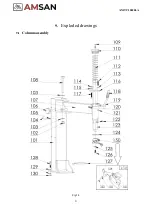
Page 22: ...Fig 34 21 AM TC10626LA 9 1 Column assembly 9 Exploded drawings ...
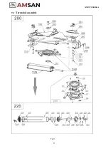
Page 23: ...Fig 35 22 AM TC10626LA 9 2 Turntable assembly ...
Page 24: ...Fig 36 22 AM TC10626LA 9 3 Gearbox motor assembly ...
Page 25: ...24 AM TC10626LA 9 4 Body assembly Fig 37 ...
Page 26: ...25 AM TC10626LA 9 5 Bead Breaker Cylinder Breaker Arm Assembly Fig 38 ...
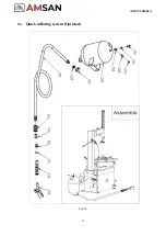
Page 27: ...26 AM TC10626LA 9 6 Quick inflating system Optional Fig 39 ...
Page 28: ...27 AM TC10626LA 9 7 Simple left help arm Optional Fig 40 INSTALL ...
Page 41: ...40 AM TC10626LA Appendix 1 Electrical Diagram Fig 40 Fig 41 ...


