16
AM-TC10626LA
6.
Maintenance
Note
:
Only the specialized technician can do the maintenance. Before any maintenance is performed, disconnect
the power and keep the plug within the sight of the maintenance personnel. and shut off compressed air, push
the air valve switch to “Off” position and depress pedal 16 for 3 or 4 times to bleed the residual compressed
air in the machine
To keep the tire change in good condition and to prolong the work life, it is necessary to do regular maintenance
according to the instructions on the user’s manual. Otherwise, the normal operation and reliability of the
machine will be affected, or personal injury would be caused.
⚫
Keep the machine and working area clean and prevent dust or foreign matter from entering the moving
parts.
⚫
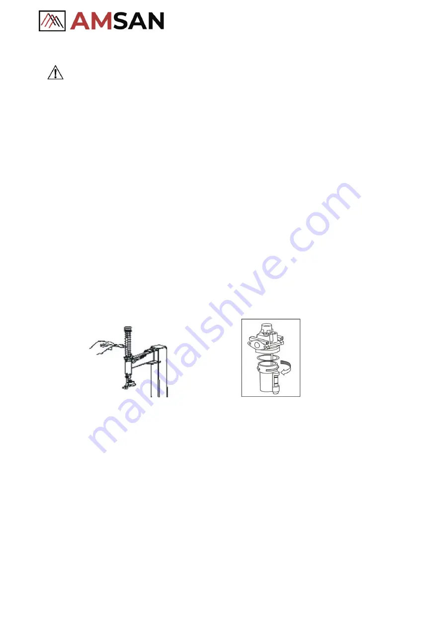
Keep the hexagonal column and the moving parts clean and lubricate
(
clean with diesel as Fig.26
)
.
⚫
Keep the swing arm clean and lubricate it periodically so that it can move expectably.
⚫
Check the oil level in the sprayer regularly. If the oil level does not reach the second line, fill SAE20
(Fig.27).
⚫
Clear away the condensed material in the water separator around the sprayer regularly.
⚫
Regularly check and adjust the tension of the belt.
⚫
Check all connecting parts and bolts regularly and tighten them if necessary.
⚫
Check and adjust locker handle periodically, to make sure after locking, mount head and rim keep 2-3m
distance.
Fig.26
Fig.27
7.
Storing and Scrapping
7.1.
Storing
When the equipment needs to be stored for a long time.
⚫
Disconnect the power and compressed air.
⚫
Lubricate all the parts: slide block and groove.
⚫
Empty all the oil/liquid cups.
⚫
Cover the equipment with a plastic shield.
7.2.
Scrapping
When the equipment can no longer be used, disconnect the power and compressed air and dispose of them by
the local regulations.
Summary of Contents for AM-TC10626LA
Page 1: ...PLEASE READ THE PRODUCT MANUAL ENTIRELY BEFORE INSTALLING OR OPERATING THE LIFT ...
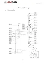
Page 22: ...Fig 34 21 AM TC10626LA 9 1 Column assembly 9 Exploded drawings ...
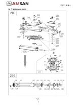
Page 23: ...Fig 35 22 AM TC10626LA 9 2 Turntable assembly ...
Page 24: ...Fig 36 22 AM TC10626LA 9 3 Gearbox motor assembly ...
Page 25: ...24 AM TC10626LA 9 4 Body assembly Fig 37 ...
Page 26: ...25 AM TC10626LA 9 5 Bead Breaker Cylinder Breaker Arm Assembly Fig 38 ...
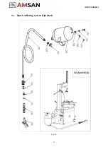
Page 27: ...26 AM TC10626LA 9 6 Quick inflating system Optional Fig 39 ...
Page 28: ...27 AM TC10626LA 9 7 Simple left help arm Optional Fig 40 INSTALL ...
Page 41: ...40 AM TC10626LA Appendix 1 Electrical Diagram Fig 40 Fig 41 ...


