29
AM-TC10626LA
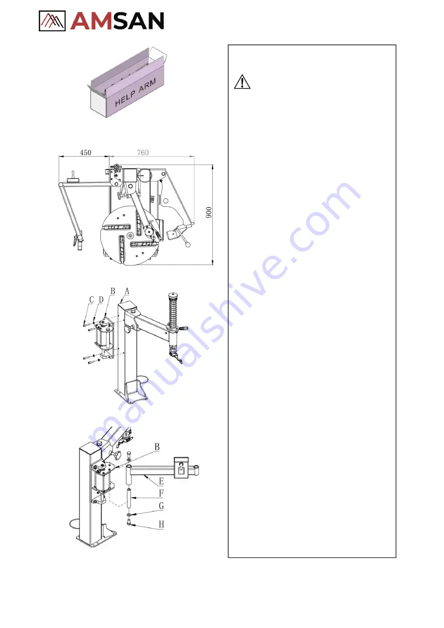
Fig
.2
Fig
.3
Fig
.4
Fig
.5
Installation, air connection, and
testing
NOTE
:
➢
This arm must be used together with
t h e tire changer machine appointed
by the manufacturer
.
➢
The installation of this auxiliary device
should
be
done
by
professional
personnel
.
➢
Before assembly, disconnect the device
from the power supply and air source
1
Unpacking
(
Fig.2
)
⚫
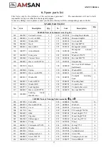
When unpacking, check to make sure all
parts shown on the packing list are
included. If any parts are missing or
broken, please call the manufacturer or
the dealer as soon as possible. Please
keep the package out of children’s reach.
2 Location size
(
Fig.3
)
⚫
Leave enough space for the operation
and maintenance of this arm. Keep no
less than 500MM distance around for
operation area.
3
Installation
⚫
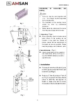
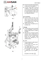
Fix base B onto the left side of post-
A with 4 pieces screw M10*45 C and
washer D (as
Fig
.4)
⚫
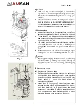
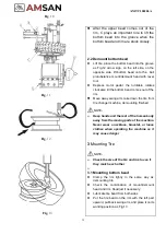
Remove F from B and put F into E
as. Fig.5, fix arm E into base B with
screw H (M16*30) and washer G,
fasten it, make sure arm E can be
moveable in the horizontal direction.
Summary of Contents for AM-TC10626LA
Page 1: ...PLEASE READ THE PRODUCT MANUAL ENTIRELY BEFORE INSTALLING OR OPERATING THE LIFT ...
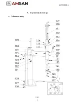
Page 22: ...Fig 34 21 AM TC10626LA 9 1 Column assembly 9 Exploded drawings ...
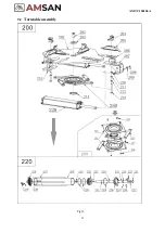
Page 23: ...Fig 35 22 AM TC10626LA 9 2 Turntable assembly ...
Page 24: ...Fig 36 22 AM TC10626LA 9 3 Gearbox motor assembly ...
Page 25: ...24 AM TC10626LA 9 4 Body assembly Fig 37 ...
Page 26: ...25 AM TC10626LA 9 5 Bead Breaker Cylinder Breaker Arm Assembly Fig 38 ...
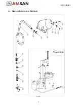
Page 27: ...26 AM TC10626LA 9 6 Quick inflating system Optional Fig 39 ...
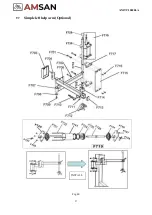
Page 28: ...27 AM TC10626LA 9 7 Simple left help arm Optional Fig 40 INSTALL ...
Page 41: ...40 AM TC10626LA Appendix 1 Electrical Diagram Fig 40 Fig 41 ...


