30
AM-TC10626LA
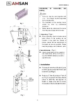
Fig
.6
Fig
.7
⚫
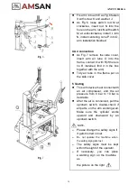
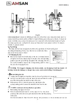
Fix arm I into arm E as Fig.6 fasten
it with screw K and washer J.
⚫
As Fig.6, loose switch rod M at
clockwise, insert rod N into the
hole on the arm, lock N with switch
M at anti-clockwise, install L into
N, install centering cone P into O,
arm installation finished.
4 Air connection
⚫
As Fig.7 remove the side cover,
insert arm air tube O into the
frame, connect it with R(if there is
no R installed, find it in the box
together with the arm)
⚫
Tidy air tube in the frame put on
the side cover.
5 Testing
⚫
This arm device must connect with
an air compressor, and the air
pressure from 8 bar to 10 bar is
desirable.
⚫
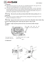
After the air is connected, pull the
up/down switch, double-check if
all parts on the arm working well.
Make sure the cylinder works
upward and downward by an
up/down switch.
NOTE
:
➢
Please change the safety signs if
it gets blurred or lost
.
➢
Do not operate the machine when
the safety sign gets lost
.
➢
The safety signs must be kept
within the sight of the operator
.
➢
If necessary, you can place
a warning sign on the machine
as
the picture on the right
Summary of Contents for AM-TC10626LA
Page 1: ...PLEASE READ THE PRODUCT MANUAL ENTIRELY BEFORE INSTALLING OR OPERATING THE LIFT ...
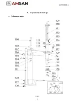
Page 22: ...Fig 34 21 AM TC10626LA 9 1 Column assembly 9 Exploded drawings ...
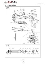
Page 23: ...Fig 35 22 AM TC10626LA 9 2 Turntable assembly ...
Page 24: ...Fig 36 22 AM TC10626LA 9 3 Gearbox motor assembly ...
Page 25: ...24 AM TC10626LA 9 4 Body assembly Fig 37 ...
Page 26: ...25 AM TC10626LA 9 5 Bead Breaker Cylinder Breaker Arm Assembly Fig 38 ...
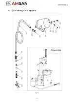
Page 27: ...26 AM TC10626LA 9 6 Quick inflating system Optional Fig 39 ...
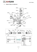
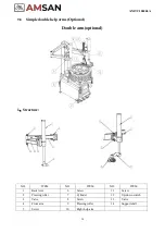
Page 28: ...27 AM TC10626LA 9 7 Simple left help arm Optional Fig 40 INSTALL ...
Page 41: ...40 AM TC10626LA Appendix 1 Electrical Diagram Fig 40 Fig 41 ...

