AM-TC10626LA
31
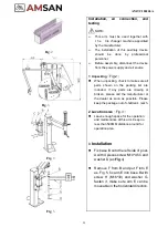
Fig
.8
Fig
.9
Operation
⚫
This help arm has been designed to facilitate the
operations of tire mounting/demounting. In any case,
this device would make these jobs easier on any type
of wheel.
⚫
All work on the electrical system, including minor operations,
must be carried out by professionally qualified personnel
!
Check that the electrical supply voltage and air supply is the
same as that indicated on the plate of the machine
1 Rim clamping
⚫
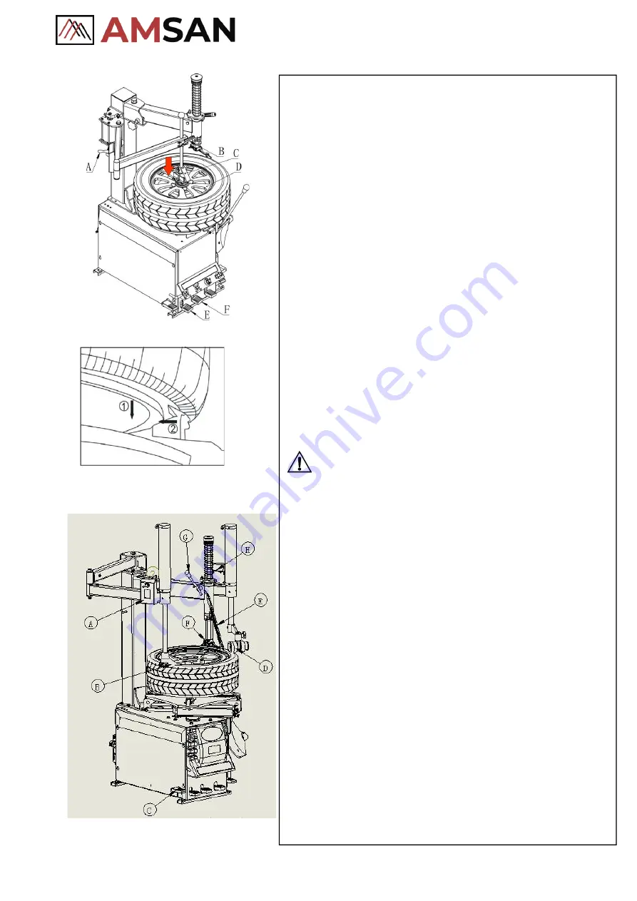
As per the instruction on the manual, lose the tire from
its two sides with a shovel and lubricate the tire bead
⚫
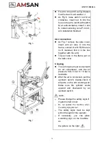
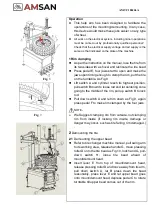
Press pedal E, four jaws start to open and make the
jaws open till big enough to clamp the rim, put the tire
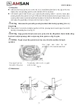
on the turntable. As Fig 8
⚫
Lift switch A and cylinder reach its highest position,
pull switch B down to loose rod and let centering cone
going to the middle of the rim, pull up switch B to lock
rod.
⚫
Pull down switch A and let rim down as Fig,9, again
press pedal F to make rim clamped by the four jaws.
NOTE
:
➢
We Suggest clamping rim from outside, not clamping
rim from inside (if locking rim inside, damage or
danger may occur, such as tire falling, rim damaged.)
。
2
Demounting the tire
2.1
Demounting the upper bead
⚫
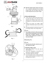
Refer to tire changer machine manual, pull swing arm
to its working area, release handle G, move pressing
roller D onto the tire bead as Fig.10, lock hand G, pull-
down switch H, loose tire bead ahead of
mount/demount head.
⚫
Insert lever E from top of mount/demount head,
release pressing roller D and move away from its arm,
pull down switch A, let B press down tire bead
reasonably, press lever E and let upper bead goes
onto mount/demount head, depress pedal C to rotate
turntable till upper bead comes out of the rim.
Summary of Contents for AM-TC10626LA
Page 1: ...PLEASE READ THE PRODUCT MANUAL ENTIRELY BEFORE INSTALLING OR OPERATING THE LIFT ...
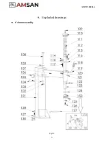
Page 22: ...Fig 34 21 AM TC10626LA 9 1 Column assembly 9 Exploded drawings ...
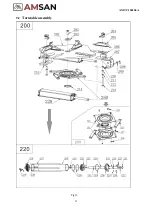
Page 23: ...Fig 35 22 AM TC10626LA 9 2 Turntable assembly ...
Page 24: ...Fig 36 22 AM TC10626LA 9 3 Gearbox motor assembly ...
Page 25: ...24 AM TC10626LA 9 4 Body assembly Fig 37 ...
Page 26: ...25 AM TC10626LA 9 5 Bead Breaker Cylinder Breaker Arm Assembly Fig 38 ...
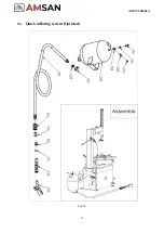
Page 27: ...26 AM TC10626LA 9 6 Quick inflating system Optional Fig 39 ...
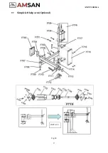
Page 28: ...27 AM TC10626LA 9 7 Simple left help arm Optional Fig 40 INSTALL ...
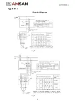
Page 41: ...40 AM TC10626LA Appendix 1 Electrical Diagram Fig 40 Fig 41 ...

