32
AM-TC10626LA
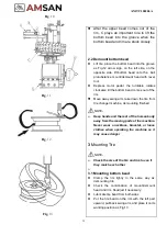
Fig
.10
Fig
.11
Fig
.12
⚫
After the upper bead comes out of the
rim, C plays an important role to lift the
bottom bead into the groove when the
bottom bead and rim are stuck closely.
2.2 Demount bottom bead
⚫
Lift tire, place the bottom bead into the groove
as Fig.12 arrow sign, on the left side, on the
opposite side, lift bottom bead onto the ball
protuberance mount/demount head with lever
tool.
⚫
Depress motor pedal, the turntable rotates
clockwise till the bottom bead comes out of the
rim.
⚫
Move away swing arm, take down the tire from
tire changer machine, demounting finished.
NOTE
:
➢
Keep hands and the rest of the human body
away from the moving parts of the machine.
Never wear a necklace, bracelet, or loose
clothes when operating the machine as it
may cause danger
3
Mounting Tire
NOTE
:
➢
Check the size of the tire and rim to see if
they match each other
Fig
.13
➢
3.1 Mounting bottom bead
⚫
Clamp the rim tightly in the same way as
demounting tire.
⚫
Check the coordination of mount/demount
head and rim. Readjust if necessary.
⚫
Lubricate tire bead from both sides
⚫
Put the tire bead on the rim with the left part
upward, pull back swing arm, and place it on its
working position as Fig.13
Summary of Contents for AM-TC10626LA
Page 1: ...PLEASE READ THE PRODUCT MANUAL ENTIRELY BEFORE INSTALLING OR OPERATING THE LIFT ...
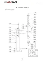
Page 22: ...Fig 34 21 AM TC10626LA 9 1 Column assembly 9 Exploded drawings ...
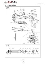
Page 23: ...Fig 35 22 AM TC10626LA 9 2 Turntable assembly ...
Page 24: ...Fig 36 22 AM TC10626LA 9 3 Gearbox motor assembly ...
Page 25: ...24 AM TC10626LA 9 4 Body assembly Fig 37 ...
Page 26: ...25 AM TC10626LA 9 5 Bead Breaker Cylinder Breaker Arm Assembly Fig 38 ...
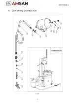
Page 27: ...26 AM TC10626LA 9 6 Quick inflating system Optional Fig 39 ...
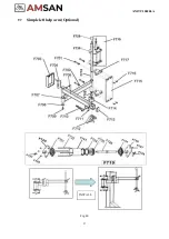
Page 28: ...27 AM TC10626LA 9 7 Simple left help arm Optional Fig 40 INSTALL ...
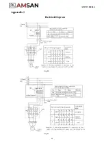
Page 41: ...40 AM TC10626LA Appendix 1 Electrical Diagram Fig 40 Fig 41 ...


