111027
-
3
-
12.
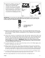
Insert the No.2 Phillips screwdriver in the
right two of the four Clearance Holes
located above the Magnetic Head
Assemblies and remove two M3 Phillips
screws [10.11] from the Write Magnetic
Head Assembly [10.12]. Carefully lift and
slide the Write Magnetic Head Assembly
out from the base of the printer. Take care
to not remove the Grounding plate [10.13].
Fig. 9
Fig. 10
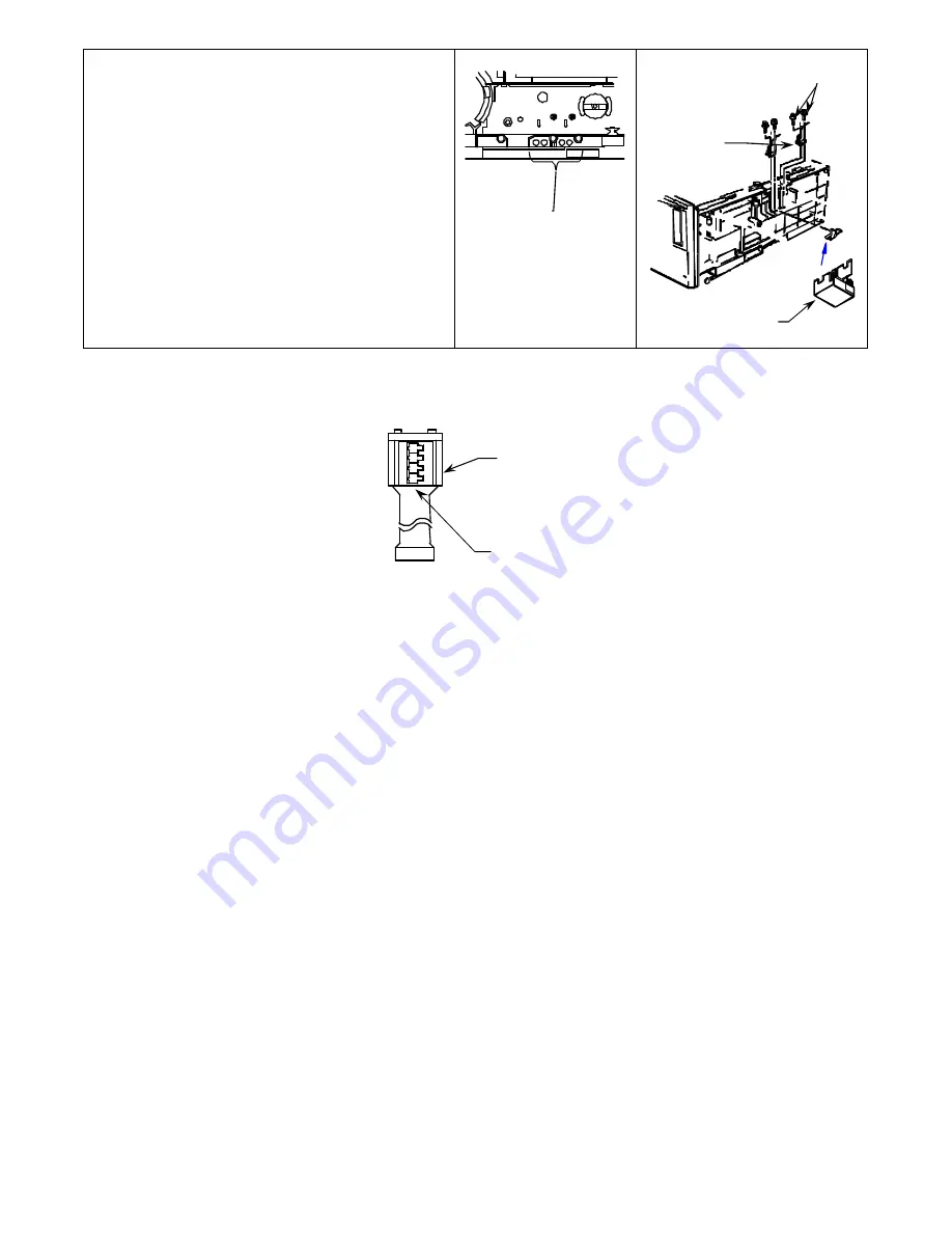
IMPORTANT
: Note the location of the Write Magnetic Head Assembly [11.12] then examine the four
rotated “T” shaped symbols on the Head Assembly. Match the symbols with the new Write Magnetic
Head Assembly prior to installing the new Head.
Fig. 11
13.
Install the new Write Magnetic Head Assembly. Place the Write Magnetic Head Assembly on the
right side of the Magnetic Head Bracket. Secure the Write Head Assembly with the two M3 Phillips
screws from step 12
.
Make sure that the Grounding Plate [10.13] is installed between the Magnetic
Head Assemblies.
14.
Connect all the connectors to the Read/Write Interface PCB Assembly starting with the white ten-pin
flat ribbon cable and ending with the Magnetic Head Assembly Cables. Insert the Print-Board Sheet
from step 11 between the Read/Write Interface PCB Assembly and the bottom printer chassis then
secure the Read/Write Interface PCB Assembly to the bottom of the printer with the seven M3
Phillips tapping screws from step 10.
IMPORTANT:
Keep the arm of sensor component extended
over the Read Magnetic Head Cable prior to securing the PCB Assembly. Failure to do so will result
in the printer displaying a Zone B Paper Jam.
15.
Assemble the Base Plate to the bottom of the printer chassis with the six M3 Phillips tapping screws
and the two M3 Phillips screws from step 9.
16.
Rotate the printer until the Service side is facing up then Slide the left end of the new Main PCB
Assembly between the Flash Card Shield and the two molded plastic standoffs. Align the connector
holes on the new Main PCB Assembly with the four Connector Guide Pins then carefully push in the
new PCB Assembly until it is completely seated on both connectors and all of the plastic standoffs.
17.
Assemble the BCR Guide to the previous location on the printer with the long M3 Phillips tapping
screw from step 8 then assemble all parts previously removed in reverse order.
18.
Close the Upper Right Side Cover then close and lock the Lower Right Side Cover.
10.11
10.12
Write
(4)
Clearance
Holes
“T” shaped symbol for the
Write Magnetic Head
Assembly
11.12
10.13


