background image


26 

AMW 12_00 

F

F

A

A

I

I

L

L

U

U

R

R

E

E

S

S


U

U

N

N

I

I

T

T


D

D

O

O

E

E

S

S


N

N

O

O

T

T


W

W

O

O

R

R

K

K


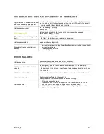
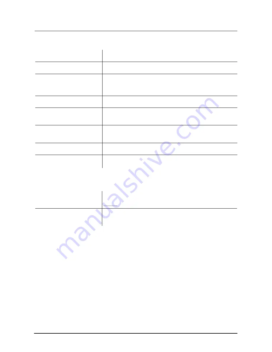
Hygrostat adjusted too high 

Adjust hygrostat at normal value = 60% 

Hygrostat defective 

Check the hygrostat on its action. 
When defective, replace it. 

Glass fuse(s) defective  

Before replacing the fuses, first determine the cause. 

 6.3A glass fuse on PCB faulty: replace by a fuse of the same value. Check 

230V exit on the PCB relay.  

 200 mA glass fuse on PCB faulty: replace by fuse of the same value. Check 

the electronic part and transformer. 

Unit gets no voltage 

Check supply cable. 

Error Code 

E1


HP regulator. 

Decrease ambient temperature if this exceeds the maximum working range 
(see technical sheet). Also check that the grids are clear and/or the fan is not 
blocked.  Reset unit by disconnecting the supply fuse and reconnect after 0.5 
min. 

Error Code 

E2 

LP regulator. 

Increase ambient temperature if lower than the minimum working range (see 
technical sheet). Also check that the grids are clear and the fan is not blocked. 
Possible leak in the cooling circuit (shortage of refrigerant).  
Reset unit by disconnecting the supply fuse and reconnect after 0.5 min. 

Error Code 

E3


TC compressor out 

For three-phase unit check that all three phases conduct. Reset unit. 

Error Code 

E4 

TC fan out 

Check filter and evaporator on contamination. Also check that the grids are 
clear and the fan is not blocked. Reset unit by disconnecting the supply fuse 
and reconnect after 0.5 min. 


U

U

N

N

I

I

T

T


R

R

U

U

N

N

S

S


C

C

O

O

N

N

T

T

I

I

N

N

U

U

O

O

U

U

S

S

L

L

Y

Y


Unit capacity too low. 

The original working circumstances can be changed: a higher water 
temperature and/or lower ambient temperature, longer use of the pool –  see 

start up

.  

Hygrostat defective or set too low. 

Replace faulty hygrostat when defective. 
Set hygrostat to higher value. Normal value: 60% RH. 


Summary of Contents for 100

Page 1: ......

Page 2: ......

Page 3: ...give many years of faultless operation but like every mechanical system a correct installation and regular maintenance are vital We reserve the right to change our products without prior notice We can never be held responsible for any errors and or omissions in this manual ...

Page 4: ......

Page 5: ...cution V 10 TRANSPORT AND UNPACKING 11 GENERAL 11 TRANSPORT 11 UNPACKING 11 REMOVING THE PALLET 11 TRANSPORT SCREWS 11 INSTALLATION DIRECTIONS 12 GENERAL 12 WORKING AREA 12 CONDENSATION DRAIN 12 WALL MOUNTING 13 INSTALLATION EXAMPLE 14 CONNECTIONS 15 HOT WATER BATTERY 15 General 15 Hydraulic Connections 15 Control 15 ELECTRICAL HEATING 16 General 16 Supply 16 Control 16 Protection thermostat 16 ...

Page 6: ...19 Dimensions 20 ELECTRICAL DATA AND SUPPLIES 22 POWER SUPPLY 22 General 22 Supply 22 Automatic system 22 CONTROLS 22 SWITCHBOARD CABINET 23 General 23 Connection terminals 23 Components 23 Connection diagram 23 PRINTING CIRCUIT BOARD 23 START UP SAFETY REGULATIONS AND MAINTENANCE 24 START UP 24 General 24 Read out 24 Error codes 24 Reset 24 SAFETY REGULATIONS 25 Frost 25 Protection volume 25 Air ...

Page 7: ...FAILURES 26 UNIT DOES NOT WORK 26 UNIT RUNS CONTINUOUSLY 26 UNIT WORKS BUT DOES NOT DEHUMIDIFY OR INADEQUATE 27 OTHER FAILURES 27 ...

Page 8: ......

Page 9: ...ndensation tank Expansion valve with distribution head for several injections Combi dryer combination of filter dryer sight glass and liquid reservoir High and low pressure thermostats Electronic control with shut off at LP HP TC and TF LP low pressure HP high pressure TC thermal contact compressor TF thermal contact fan The cooling circuit is pre filled with Forane 407C which is a CFC free coolan...

Page 10: ...ition Synthetic fibres stiffed with supporting wire gauze in a galvanized frame Class EU2 Gravimetric efficiency 65 80 Filter dimensions per type S SW WI IT TC CH HB BO OA AR RD D C CA AB BI IN NE ET T The switchboard cabinet is built inside the unit when removing the housing on the left side panel view from the back Completely pre wired according CE standards W WE EI IG GH HT TS S Weights are net...

Page 11: ... wall HOT WATER BATTERY BUILT IN THREE WAY VALVE ELECTRICAL HEATING ELECTRICAL DEFROST SWIMMING POOL CONDENSER OUTDOOR CONDENSER OUTDOOR EXECUTION REPLACEMENT FILTER Air filter to replace soiled or worn filter EXTENSION PIECES WALL DUCTS Available in two executions Depth 250 upto 500 mm Depth 500 upto 1000 mm ...

Page 12: ...m MINIMUM BUILT IN THERMOSTAT Built in thermostat for minimum temperature limitation MAXIMUM BUILT IN THERMOSTAT Built in thermostat with gold contacts for maximum temperature limitation or control of the swimming pool condenser We recommend to submit the fan to continuous running continuous measuring bridge 7 and 8 CLOCK THERMOSTAT Thermostat with week clock for night lowering in combination with...

Page 13: ...0 142M 1530 341 651 135 905 VAR 22 X WALL DUCTS VAR iable adaptable standard 100 mm extendable to maximum 170 mm OPTION EXTENSION PIECES WALL DUCTS B L P H W C coaxial condensor Y condensation drain E electrical connections d c X B L H 51 160 160 245 108 87 110 40 48 40 40 40 70 59 25 F F F F F B D D D B Ø 23 5 mm D Ø 21 5 mm F Ø 28 3 mm Y B C E ...

Page 14: ...41 1071 135 905 VAR 22 X WALL DUCTS VAR iable adaptable standard 100mm extendable to maximum 170mm OPTION EXTENSION PIECES WALL DUCTS B L P H W C coaxial condensor Y condensation drain E electrical connections d c X B L H 51 160 160 245 105 87 110 40 48 40 40 40 70 59 25 F F F F F B D D D B Ø 23 5 mm D Ø 21 5 mm F Ø 28 3 mm B Y E C ...

Page 15: ...g term storage 12 hours If the units must be moved in another way other precautions must be taken to prevent damage to the housing I IG GN NO OR RI IN NG G T TH HE ES SE E G GU UI ID DE EL LI IN NE ES S C CA AN N C CA AU US SE E D DA AM MA AG GE E U UN NP PA AC CK KI IN NG G When cutting the packaging always avoid damage to the unit Plastic cardboard and wood should be removed separately for later...

Page 16: ...tion of the unit ensure there is sufficient space to allow practical and safe maintenance to the unit back side of the unit However electrical and hydraulic connections have to be done through the side of the unit C CO ON ND DE EN NS SA AT TI IO ON N D DR RA AI IN N The condensation drain is connected via the bottom of the unit The condensation outlet is a 22 mm Ø flexible hose which must be conne...

Page 17: ... FR RO OM M T TH HE E F FL LO OO OR R Position of grate fins to be set as follows Outlet grate upper grate fins to be aligned upwards Suction grate lower grate fins to be aligned downward It is always recommend installing the unit vibration free with the optional L console L CONSOLE Including vibration isolation material C CE EI IL LI IN NG G M MO OU UN NT TI IN NG G A AN ND D I IN NS ST TA AL LL ...

Page 18: ...14 AMW 12_00 I IN NS ST TA AL LL LA AT TI IO ON N E EX XA AM MP PL LE E ...

Page 19: ...d with a three way valve HYDRAULIC CONNECTIONS Fitted with nipple connection to the LPHW The optional three way valve is external On the LPHW the IN and OUT are marked LPHW IN and LPHW OUT CONTROL ELECTRICAL CONNECTIONS SEE DIAGRAM The LPHW is controlled independently of the CH via the built in 24V control When the dehumidifier functions the fan also moves air over the LPHW The thermostat TH or hy...

Page 20: ...2P 40A 4P 20A CONTROL ELECTRICAL CONNECTIONS SEE DIAGRAM Via the thermostat or hygrothermostat the unit control is ordered to heat the fan comes in as well as the one stage control PROTECTION THERMOSTAT The resistors are always fitted with a safety thermostat which disconnects the resistors when the air temperature exceeds 85 C The resistors can only be reconnected when the temperature has dropped...

Page 21: ...E EN NT T I IN NS ST TA AL LL LA AT TI IO ON N C CH HE EM MI IC CA AL L O OR R E EL LE EC CT TR RO OL LY YT TI IC C 1 Filter installation 2 Throttling valve 3 Shut off cock C Swimming pool condenser The IN and OUT are marked COAX IN and COAX OUT The throttling valve must be turned such that the temperature difference between IN and OUT is 8 C We recommend using a heat and pressure resistant line f...

Page 22: ... 36 Dimensions L mm 730 D mm 873 H mm 714 1 Capacities are given in Watt for Δt 15K 2 Sound pressure level at 10 m 6dB at 5m in a free field semi reverberant field CONTROL ELECTRICAL CONNECTIONS SEE DIAGRAM Via a maximum thermostat at excess temperature the unit control will be ordered to emit extra heat to the outdoor condenser If also a swimming pool condenser is foreseen he extra heat is divert...

Page 23: ...tion NEN EN 13501 1 2002 EXECUTION The AMW outdoor execution can only be executed when using thermal profiles The filter is accessible when unscrewing the back side E EX XC CE EP PT T T TH HE E M MA AI IN NT TE EN NA AN NC CE E P PA AN NE EL L A AL LL L J JO OI IN NT TS S H HA AV VE E T TO O B BE E S SE EA AL LE ED D W WI IT TH H S SI IL LI IC CO ON NE ES S P PR RO OV VI ID DE ED D T TO OG GE ET T...

Page 24: ...m B mm H mm c d e X B C Y 65 92M 100 1400 450 775 175 700 525 VAR 22 140 142M 1600 450 775 175 900 525 VAR 22 B L P H W C coaxial condensor Y condensation drain B electrical connections H B Y C E 110 115 c d e L B 105 40 195 X 160 105 160 105 105 40 40 40 40 110 ...

Page 25: ...H mm c d e X B C Y 65 92M 100 V 970 450 1135 135 700 505 VAR 22 140 142M V 1170 450 1235 135 900 605 VAR 22 B L P H W C coaxial condensor Y condensation drain E electrical connections H c d c L B Y C E 110 115 105 40 195 110 40 40 40 40 105 160 105 160 e B X ...

Page 26: ...unit AUTOMATIC SYSTEM A multi polar automatic unit with at least 3 mm contact opening is placed on the supply This must be adapted to the maximum current strength of the unit See technical sheet on the outside of the unit Type of unit 65 92M 100 140 142M Voltage V 230 230 3x400 N 3x400 N 230 Nominal A 6 9 9 4 1 4 11 4 To be foreseen Fuses A 2P 20A 2P 20A 4P 20A 4P 20A 2P 25A Always use slow fuses ...

Page 27: ...HE E A AR RT T I IN N A AC CC CO OR RD DA AN NC CE E W WI IT TH H T TH HE E C CE E S ST TA AN ND DA AR RD DS S A AN ND D E EX XE EC CU UT TE ED D B BY Y A A R RE EG GI IS ST TE ER RE ED D I IN NS ST TA AL LL LE ER R T TH HE EY Y A AR RE E T TH HE ER RE EF FO OR RE E N NE EV VE ER R O OU UR R R RE ES SP PO ON NS SI IB BI IL LI IT TY Y COMPONENTS All components used except the circuit board CDH prod...

Page 28: ...r temperature A A D DE EL LA AY Y T TI IM ME E O OF F 1 10 0 1 15 5 M MI IN NU UT TE ES S P PR RE EV VE EN NT TS S T TH HE E C CO OM MP PR RE ES SS SO OR R F FR RO OM M R RE ES ST TA AR RT TI IN NG G T TH HE E D DE EL LA AY Y T TI IM ME E S ST TA AR RT TS S E EV VE ER RY Y T TI IM ME E T TH HE E C CO OM MP PR RE ES SS SO OR R S SW WI IT TC CH HE ES S O OF FF F C CO OM MP PR RE ES SS SO OR R C CA A...

Page 29: ...ET The intake and outlet grids should always be clear Blocked grids can lead to a reduction in air flow which causes the unit to switch into safety mode where it can only be restarted after manual reset M MA AI IN NT TE EN NA AN NC CE E FILTERS All types are equipped with air filters On start up a lot of building dust can be drawn in so it is recommended that after a few weeks from starting up a n...

Page 30: ...nnect after 0 5 min Error Code E2 LP regulator Increase ambient temperature if lower than the minimum working range see technical sheet Also check that the grids are clear and the fan is not blocked Possible leak in the cooling circuit shortage of refrigerant Reset unit by disconnecting the supply fuse and reconnect after 0 5 min Error Code E3 TC compressor out For three phase unit check that all ...

Page 31: ...ature too low lower than the minimum working range higher ambient temperature Expansion valve defective Loss of refrigerant O OT TH HE ER R F FA AI IL LU UR RE ES S Unit looses water Check that the unit is levelled and adjust if necessary The outlet should be laid running downward to the drain Unit looses water and the drain is clogged Obstruction either in de drain of the condensation tank or in ...

Reviews: