Installation
17
6" Color Video Touch Panels
Wiring guidelines
The touch panel requires 12 VDC power to operate properly. The touch panel can use either a
PS(N)2.8 (if the power is being supplied only to the touch panel) or a PSN6.5 power supply (if the
power is being routed through the touch panel to power another device). The Central Controller
supplies power via the AXlink cable or external 12 VDC power supply. The maximum wiring
distance between the Central Controller and touch panel is determined by power consumption,
supplied voltage, and the wire gauge used for the cable. The table below lists wire sizes and the
maximum lengths allowable between the touch panel and Central Controller. The maximum wiring
lengths for using AXlink power are based on a minimum of 13.5 volts available at the Central
Controller’s power supply. Refer to the
Specifications
section on page 1 for more information.
If you install the touch panel farther away from the Central Controller than recommended in the
Wiring Guidelines @ 610 mA table, connect an external 12 VDC power supply to the panel, as
shown in FIG. 18 and FIG. 19.
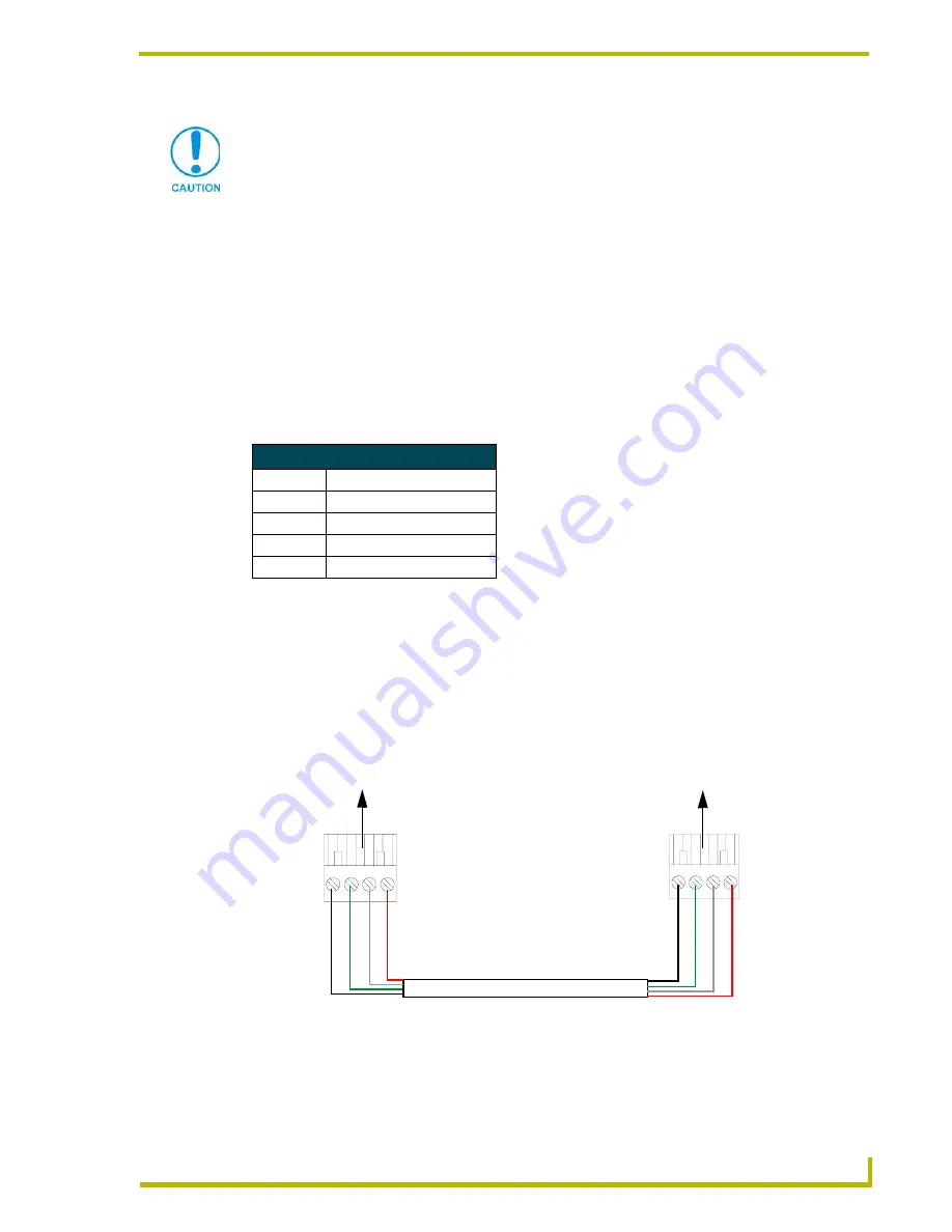
Using the 4-pin AXlink connector for data and power
Connect the Central Controller’s AXlink Phoenix connector to the AXlink connector on the touch
panel for data and 12 VDC power, as shown in FIG. 18.
Do not connect power to the touch panel until wiring is complete. If you are using a
12 VDC power supply, apply power to the touch panel only after installation is
complete.
Wiring Guidelines @ 610 mA
Wire Size
Maximum Wiring Length
18 AWG
192.41 feet (58.65 m)
20 AWG
121.73 feet (37.10 m)
22 AWG
75.90 feet (23.13 m)
24 AWG
47.84 feet (14.58 m)
FIG. 18
AXlink connector wiring diagram (direct data and power)
To the Touch Panel’s
To the external Controller device
AXlink/PWR connector
PWR +
AXP
/TX
AX
M
/R
X
GND -
Top view
Top view
PWR +
AX
P/TX
AX
M/RX
GND -


