Installation
18
6" Color Video Touch Panels
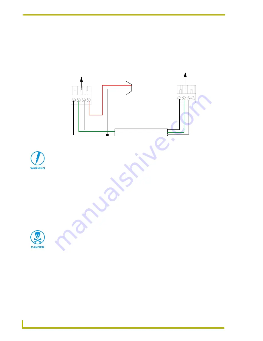
Using the 4-pin AXlink for data with external power supply
To use the AXlink 4-pin Phoenix connector for data communication (with the Central Controller)
and power transfer (from a power supply), the incoming PWR and GND cable from the power
supply must be connected to the AXlink cable connector going to the touch panel. FIG. 19 shows
the external power supply diagram.
Make sure to connect only the GND wire on the AXlink/PWR connector when using a separate
12 VDC power supply. Do not connect the PWR wire to the AXlink connector’s PWR (+)
opening.
1.
Unscrew the PWR and GND wires on the terminal end of the power supply’s 2-pin cable.
2.
Pair the GND wires from the power supply and Central Controller AXlink connectors together;
insert them into the clamp position for GND on the touch panel AXlink connector.
3.
Tighten the clamp and secure the two GND wires.
4.
Place the PWR wire from the power supply into the open clamp position for PWR on the touch
panel AXlink connector.
FIG. 19
AXlink connector wiring diagram (using external power source)
PWR (+)
GND (-)
Local +12 VDC
(coming from
To the Touch Panel’s
To the external Controller device
AXlink/PWR connector
power supply
the power
supply)
Top view
Top view
AX
P/
TX
AXM/
R
X
GN
D -
A
XP/
TX
AXM/
R
X
GND -
When you connect an external power supply, do not connect the wire from the PWR
terminal (coming from the external device) to the PWR terminal on the Phoenix
connector attached to the Controller unit. Make sure to connect
only
the AXM, AXP,
and GND wires to the Controller’s Phoenix connector when using an external power
supply.
Never connect both power wires from the power supply and Central Controller to the
PWR terminal on the touch panel AXlink connector. Only the power supply PWR wire
should be connected to the touch panel AXlink connector. If both sources are used to
provide power to the touch panel, an electrical hazard is created and the threat of
both equipment damage and personal injury is likely.


