Accessories
24
MVP-5200i Modero® ViewPoint® Touch Panel with Intercom - Instruction Manual
8.
Firmly seat the mini-captive wire connector to the power connector on the device.
9.
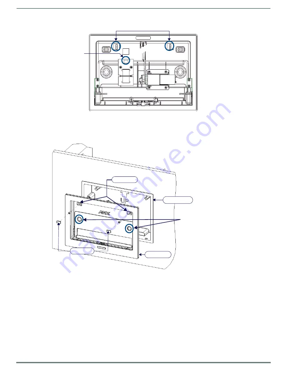
Firmly seat the device against the box. Make sure that the tab connector at the top of the device is locked into the box.
10. Insert the two installation screws from the MVP-WCS-52 Installation Kit into the screw holes in the interior compartment of
the device and tighten them to anchor the device to the box (FIG. 13).
NOTE:
For ease of installation, put each screw on a neodymium magnet in the device’s interior compartment to keep them on
hand until they are needed.
11. After fully seating the screws, wipe down the area around the screw holes with the alcohol prep pad from the Installation Kit.
Take a rubber foot and remove its adhesive backing. Put the foot, adhesive-side down, in the slot surrounding the screw hole
in the Wall Charging Station. Press down firmly to remove any air bubbles from underneath the foot.
12. Install an MVP-5200i device by placing it into the interior compartment bottom-first. Press the top of the touch panel until it
is flush with the Wall Charging Station. The neodymium magnets will hold it in place.
13. To remove the MVP-5200i, unlock the touch panel (see the
Unlocking the Touch Panel
section on page 22 for more
information) and wait for the touch panel to pull away from the Wall Charging Station. Once it has been released, grip it by the
top of the device, and pull it free from the Charging Station.
FIG. 12
MVP- WCS-52 - Rear view
FIG. 13
Installation of MVP-WCS-52
Tie-Wrap Anchors
Mini-Captive Wire
Connector (female)
Neodymium magnets
Plastic back box
Rubber feet
Screw holes
MVP-WCS-52


