Upgrading Firmware
72
MVP-5200i Modero® ViewPoint® Touch Panel with Intercom - Instruction Manual
Upgrading Firmware
Overview
For the purpose of panel downloads, the MVP-5200i’s download procedure is not compatible with other AMX panel devices. This is
due to the unique configuration of the device.
The first major change from other AMX devices is that the MVP-5200i uses dynamic Setup Pages for its displays. Instead of
requiring a separate Setup Page project built within TPDesign 4, the MVP-5200i uses only a single set of Setup Pages for all of its
supported resolutions.
To enable a single Setup Page project to support all resolutions, this requires including images for the largest supported resolution
with the Setup Page project and scaling the images to fit for lower resolutions. This modification would apply to state-level bitmaps
and chameleon images; previously, image scaling has only applied to dynamic images.
These features require a separate G4SupportFiles installation to be posted for download independently of the TPDesign4, NetLinx
Studio, and Visual Architect applications.
Scale Images For Setup Pages
To provide the Setup Page designer with the ability to design pages at the target device’s lowest supported resolution, TPDesign4
performs image scaling for both standard and chameleon images for button and page states. This functionality is not extended to
icon images.
The MVP-5200i comes already loaded with on-board firmware, which is upgradeable through the use of the latest version of
NetLinx Studio. Refer to the
NetLinx Studio version 2.x or higher Instruction Manual
for more information on how to download
firmware to a touch panel.
NOTE:
Programming the MVP-5200i requires the use of the latest versions of NetLinx Studio and TPDesign 4, both available from
www.amx.com.
The MVP-5200i uses a native RNDIS USB driver for USB-over-Ethernet communication. When the device is connected to the
downloading computer (see instructions below for more details), it creates a new LAN connection, and the user will need to supply
a static IP address for this to be enabled. To enter a static IP address, the user must edit the properties of the TCP/IP interface of
the connection itself. This driver is included in the installation of the latest version of NetLinx Studio, available from
www.amx.com
.
Upgrading the Modero Firmware via the USB port
The MVP-5200i uses a 5-pin CC-USB (Type A) to Mini-B 5-Wire programming cable (
FG10-5965
) for programming, firmware
updates, and touch panel file transfer between the PC and the target device. If a programming cable is not available, it may be
purchased from
www.amx.com
. The Mini-USB port for the connector is located on the left side of the device as viewed from the
front.
Before beginning with this section, verify that the device is powered and the Type-A end of the USB connector is inserted and
secure in the PC’s USB port.
The panel must be powered
On
before connecting the mini-USB connector to the panel.
To
guarantee that the upgrade is not interrupted by power loss, connecting the device to a power source, such as inserting it into a
Table Charging Station, before beginning the upgrade is highly recommended.
NOTE:
Establishing a USB connection between the PC and the panel, prior to installing the USB Driver, will cause a failure in the USB
driver installation.
1.
Launch NetLinx Studio and select
Settings
>
Master Communication Settings
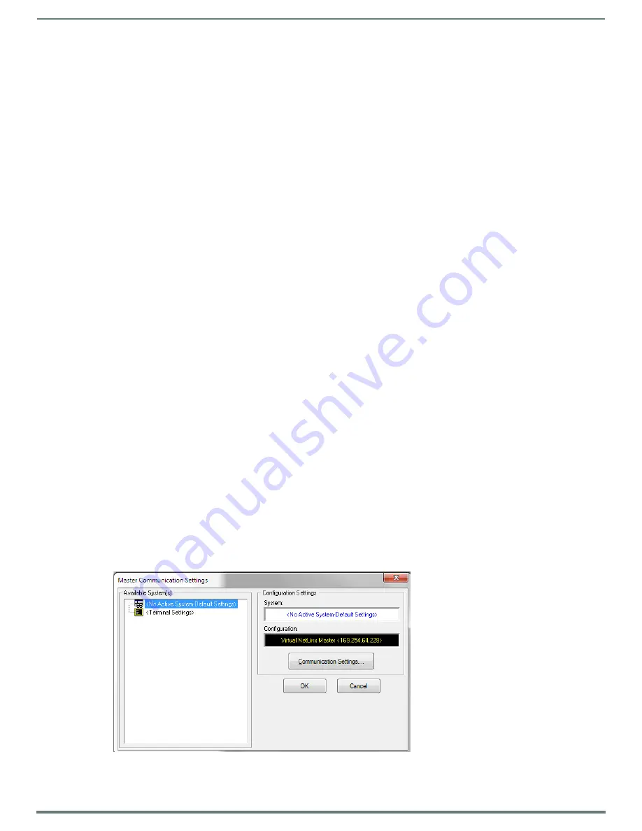
from the Main menu to open the
Master
Communication Settings
dialog (FIG. 73). If this is the first time the device needs to be configured, refer to the
Configuring
Modero Firmware via the USB Port
section on page 186.
2.
Click the
Communications Settings...
button to open the
Communications Settings
dialog (FIG. 74).
FIG. 73
Master Communications Settings dialog


