NetLinx Programming
16
NXB-KNX KNX Communications Gateway
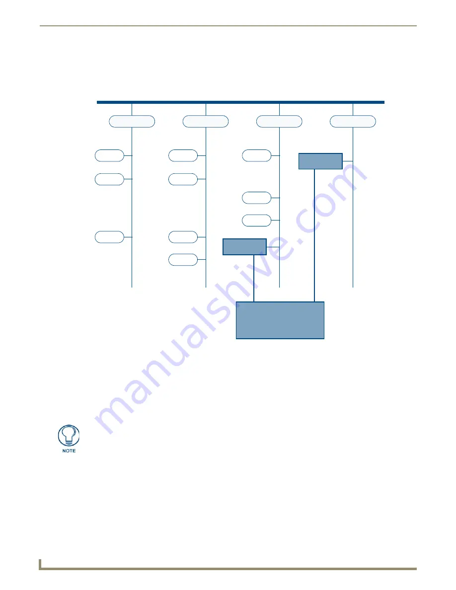
KNX Bus Diagram
The NXB-KNX is a transparent KNX device and can be connected at any location with the KNX.
In contrast to simple actuators and sensors, the NXB-KNX may be responsible for up to 3,000 Destination Addresses
(where a normal dimmer only responds to four Destination Addresses). FIG. 22 provides a basic diagram of a KNX Bus:
It is important to ensure that the NXB-KNX can respond to all bus Telegrams in question. When using line couplers,
careful planning is necessary. The following should be considered:
Bus Telegrams have to reach the NXB-KNX. If line couplers are inserted between NXB-KNX and the
component to be controlled, then the filter tables of the line couplers must be programmed to pass on all
relevant Telegrams.
Older line couplers may be slow. In this case, KNX devices will require a certain amount of time between
receiving Telegrams.
The situation with the NXB-KNX is different: the NXB-KNX can read all Telegrams, even with high bus load.
Therefore, it is crucial that activated Actuators are given sufficient time to respond.
Notes on Line Couplers
Telegrams must be intelligently sent across KNX lines by line couplers.
Line couplers prevent Telegrams within a line from adding traffic load outside its line.
Line couplers also filter out cross-line Telegrams if its line is not the destination line.
FIG. 22
KNX Bus Diagram
KNX Backbone
Line Coupler
Actuator
KNX Li
ne
Sensor
Actuator
Line Coupler
Actuator
Sensor
Actuator
Line Coupler
Actuator
Line Coupler
Sensor
Sensor
Sensor
KNX Li
ne
KNX Li
ne
KNX Li
ne
NXB-KNX
NXB-KNX
AMX
"Scene" modules often produce a flood of Telegrams being transmitted to all
actuators participating in the scene. Under normal circumstances these are different
devices, the down time of the line coupler does not matter - each line coupler has
enough time to recover before receiving a new Telegram.


