background image

Serial Commands

13

Solecis AVS-SL-PR-0201-0301 Presentation Switcher

Serial Commands

Communication Protocol


Baud - 9600


Data Bits - 8


Stop Bits - 1


Parity - None

Command Set 

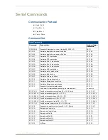
Serial Commands

Command

Description

Acknowledge 

Returned

F2 09 EA 80

Requests Solecis device code – Header 6E, 2020 = 1D

6E 1D

9F 15 05

Simulates display device power on button

9F 15 05

9F 15 06

Simulates display device power off button

9F 15 06

9F 15 07

Simulates PC1 input button

9F 15 07

9F 15 08

Simulates PC2 input button

9F 15 08

9F 15 09

Simulates Video 1 input button

9F 15 09

9F 15 0A

Simulates Video 2 input button

9F 15 0A

9F 15 0B

Simulates Video 3 input button

9F 15 0B

9F 15 0C

Simulates AUX input button

9F 15 0C

9F 15 0D

Simulates mute / blank button

9F 15 0D

9F 15 0E

Simulates Mode button

9F 15 0E

9F 15 0F

Simulates Volume up button

9F 15 0F

9F 15 10

Simulates Volume down button

9F 15 10

9F 15 11

Simulates Microphone mix button

9F 15 11

9F 15 12

Simulates Microphone mute button

9F 15 12

9F 15 13

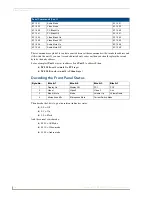
Requests front panel display status
See below for information on decoding the returned data.

9F 15 13 
xx xx xx xx

9F 15 14 VV

Sets the microphone volume (max 00 < VV < 80 min)

9F 15 14 VV

9F 15 15 01 VV Sets the microphone gain (00 < VV < FF)

9F 15 15 01 VV

9F 15 15 02 VV Sets the microphone bass (00 < VV < FF)

9F 15 15 02 VV

9F 15 15 04 VV Sets the microphone mid (00 < VV < FF)

9F 15 15 04 VV

9F 15 15 08 VV Sets the microphone treble (00 < VV < FF)

9F 15 15 08 VV

9F 15 17 VV

Sets the master volume (max 00 < VV < 80 min)

9F 15 17 VV

9F 15 18

Requests the master volume (max 00 < VV < 80 min)

9F 15 18 VV

9F 15 1A

Microphone Volume Up

9F 15 1A

9F 15 1B

Microphone Volume Down

9F 15 1B

9F 15 1C

Microphone Mix On

9F 15 1C

9F 15 1D

Microphone Mix Off

9F 15 !D

9F 15 1E

Microphone Mute On

9F 15 1E

9F 15 1F

Microphone Mute Off

9F 15 1F

9F 15 20

AV Mode

9F 15 20

Summary of Contents for Solecis AVS-SL-PR-0201-0301

Page 1: ...Operation Reference Guide Solecis Switchers AVS SL PR 0201 0301 Solecis Presentation Switcher 2x1 2 RGBHV 3x1 SVID 5x1 Stereo CP Initial Release 6 30 2008 ...

Page 2: ...rked on the outside of each box The RMA is valid for a 30 day period After the 30 day period the RMA will be cancelled Any shipments received not consistent with the RMA or after the RMA is cancelled will be refused AMX is not responsible for products returned without a valid RMA number AMX is not liable for any damages caused by its products or for the failure of its products to perform This incl...

Page 3: ...ductor on the power cord To avoid electric shock plug the power cord into a properly wired receptacle Do not defeat the purpose of the grounding type plug Fuse For protection against the risk of fire use only a fuse of the same rating and type Liquid Spills Do not set drinks on top of the unit or immerse the unit in liquid Do Not Disassemble The switcher contains no user serviceable parts All serv...

Page 4: ...Safety Instructions Solecis AVS SL PR 0201 0301 Presentation Switcher ...

Page 5: ...s a Overview 1 Product Specifications 2 Connections 5 PC Connections 5 Video Connections 5 Audio Connections 5 Microphone Connections 5 Balanced Output Connections 5 Serial Control Connections 6 Configuration 7 Overview 7 Microphone Setup 8 Display Setup 8 Sources Setup 9 Locking Buttons 9 Operation 11 Power On 11 Power Off 11 PC1 PC2 11 Video 1 2 3 11 AUX 11 Mute Blank 11 Mode 11 Volume Up Down 1...

Page 6: ...ii Solecis AVS SL PR 0201 0301 Presentation Switcher Table of Contents Serial Commands 13 Communication Protocol 13 Command Set 13 Decoding the Front Panel Status 14 Troubleshooting 15 ...

Page 7: ...ontrol for total flexibility Regardless of the video input type CV or YC both CV and YC outputs are available simultaneously which allows mixed format inputs to be displayed without switching The AVS SL PR 0201 0301 also supports a balanced microphone with phantom power if required for which the gain and tone can easily be adjusted from the PC based setup software The microphone input can be mixed...

Page 8: ... Level 5V p p Impedance 75 ohm Video Input Number 3 Connectors RCA 4 pin mini din S Video Type CV or YC Bandwidth 50 MHz 3dB Differential Phase Error 0 05 Differential Gain Error 0 03 Crosstalk 60dB 1MHz Audio Input Number 6 Level Analog Connector RCA Type Unbalanced analog Max Level 2V p p Impedance 47K ohm Audio Response 20Hz 50KHz Microphone Balanced Unbalanced Phantom Power 12V internal 48V ma...

Page 9: ...n S Video Audio Output Connector RCA Captive wire Switched 1 unbalanced with volume control Mixed 1 balanced unbalanced Impedance 600 ohm Power 110 240V 50 60Hz Power Connector IEC Power Consumption 15W Dimensions HWD 44 x 441 x 174 Weight 1 4kg Included Accessories 1U Rack mounting kit Certifications CE UL60950 FCC class B part 15 RoHS WEEE compliant ...

Page 10: ...Overview 4 Solecis AVS SL PR 0201 0301 Presentation Switcher ...

Page 11: ...udio device Microphone Connections The unit comes with an internal 12V supply for use as microphone phantom power If this is not required or a separate phantom power supply is required then make sure the phantom power supply switch is set to the off position If a separate phantom power supply is required connect it to the screw terminals labelled Power and gnd Connect the microphone to the balance...

Page 12: ...d Display Tx Rx For setting up the equipment and for remote control of the switch connect to the PC Comms Tx Rx terminals The ground terminal is shared between the two connections Don t forget to cross connect the serial devices so the TX goes to RX and RX goes to TX and GROUND goes to GROUND Please double check all connections before connecting power to the unit ...

Page 13: ... on the required port and the devices front control status will then be displayed FIG 3 FIG 3 shows the PC control panel for the AVS SL PR 0201 0301 it replicates exactly what is seen on the front of the unit Clicking on a button on the screen will have the same effect as manually pressing the equivalent button Click on the Unit Address to change the value set for installation where multiple addre...

Page 14: ...ould switch to it s composite input and if the S Video option were checked then it would switch to it s S Video input There is no option to select which PC input the display device switches to when a PC input button is pressed this will always be PC1 in the library If a different input is required then the library must be edited for the desired results Having the use power interrogation checked wi...

Page 15: ...input to video 1 would be S Video to video 2 would be composite and video 3 would also be S Video Click Back to return to the main screen Locking Buttons The lock buttons option allows you to select buttons that are disabled to the user FIG 7 The button lockout selection mode is indicated by the lock buttons control turning red and then when a control button is clicked the corresponding control al...

Page 16: ...Configuration 10 Solecis AVS SL PR 0201 0301 Presentation Switcher ...

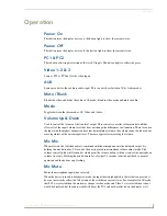
Page 17: ...e the input with the highest attenuation level reaches minimum volume the volume cannot be reduced any more regardless of the current input level The same applies for increasing the volume Mic Mix When selected the switched audio is combined with the microphone onto the balanced output By holding the mix button for 2 3 seconds the unit is placed in microphone volume adjust mode The volume control ...

Page 18: ...Operation 12 Solecis AVS SL PR 0201 0301 Presentation Switcher ...

Page 19: ...ume up button 9F 15 0F 9F 15 10 Simulates Volume down button 9F 15 10 9F 15 11 Simulates Microphone mix button 9F 15 11 9F 15 12 Simulates Microphone mute button 9F 15 12 9F 15 13 Requests front panel display status See below for information on decoding the returned data 9F 15 13 xx xx xx xx 9F 15 14 VV Sets the microphone volume max 00 VV 80 min 9F 15 14 VV 9F 15 15 01 VV Sets the microphone gain...

Page 20: ...oding the Front Panel Status Then decode the 2 bits to give the relevant indicators status 0 0 Off 0 1 On 1 0 Flash And the current switch mode 0001 AV Mode 0010 Video mode 0100 Audio mode Serial Commands Cont 9F 15 21 Audio Mode 9F 15 21 9F 15 22 Video Mode 9F 15 22 9F 15 40 PC Blank On 9F 15 40 9F 15 41 PC Blank Off 9F 15 41 9F 15 44 Video Blank On 9F 15 44 9F 15 45 Video Blank Off 9F 15 45 9F 1...

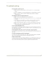
Page 21: ...display device and that there is no internal settings to allow serial communications which must first be turned on Q Can I control multiple display devices A Yes as long as they are all the same command set then you can connect the tx line from the switch to as many display device as required The rx however should only be connect to a single display device leave the rest of the displays detached Q...

Page 22: ...Troubleshooting 16 Solecis AVS SL PR 0201 0301 Presentation Switcher ...

Page 23: ...Troubleshooting 17 Solecis AVS SL PR 0201 0301 Presentation Switcher ...

Page 24: ...registered trademarks of AMX AMX reserves the right to alter specifications without notice at any time It s Your World Take Control 3000 RESEARCH DRIVE RICHARDSON TX 75082 USA 800 222 0193 469 624 8000 469 624 7153 fax 800 932 6993 technical support www amx com ...

Reviews: