Rev 05 Jun 2013 16:37 | Page 7
and
are also equipped with a single-ended RF Clock input that can receive input
frequencies from 625 MHz up to 1.5 GHz. This feature must be enabled via SPI and a clock of
appropriate frequency must be connected to the RF_CLK SMA connector. The RF Clock circuitry within
the
and
has a selectable /2 or /4 pre-divider in addition to the internal 8:1 clock
divider to facilitate usage with higher frequency clocks up to 1.5 GHz.
Clocking with the AD9525
and
boards may also be set up to be clocked from the
PDWN
To enable the power-down feature, add a shorting jumper across P3 (directly to the right of P209) at
Pin 1 and Pin 2 to connect the PDWN pin to DRVDD.
RSTB
To enable the reset feature, add a shorting jumper across P101 at Pin 1 and Pin 2 to connect the RSTB
pin to GND.
How To Use The Software For Testing
Setting up the ADC Data Capture
After configuring the board, set up the ADC data capture using the following steps:
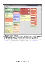
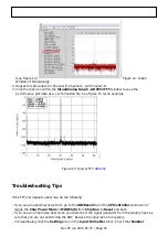
Open VisualAnalog on the connected PC. The appropriate part type should be listed in the status
1.
bar of the VisualAnalog – New Canvas window. Select the template that corresponds to the type
of testing to be performed (see Figure 3, where the

