Rev 13 May 2013 17:57 | Page 7
CR801 before entering the ADC clock inputs. The
,
with an internal 8:1 clock divider to facilitate usage with higher frequency clocks. When using the
internal divider and a higher input clock frequency, remove CR801 to preserve the slew rate of the
clock signal.
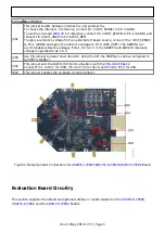
boards are set up to be clocked through
the transformer-coupled input network from the crystal oscillator, Y801. This oscillator is a low phase
noise oscillator from Valpey Fisher (VFAC3-BHL-125MHz). If a different clock source is desired, remove
C810 (optional) and Jumper J803 to disable the oscillator from running and connect the external clock
source to the SMA connector, J802 (labeled CLK+).
PDWN
To enable the power-down feature, add a shorting jumper across J204 at Pin 1 and Pin 2 to connect
the PDWN pin to DRVDD.
Modes of Operation
Standalone (PIN) Mode
ADCs can operate in pin mode if there is no need to program and
change the default modes of operation via the SPI. For applications that do not require SPI mode
operation, the CSB pin is tied to AVDD, and the SDIO/OLM pin controls the output lane mode. Table 2
and Table 3 specify the settings for pin mode operation.
Table 2. Output Lane Mode (OLM) Pin Settings
OLM Pin Voltage Output Mode
AVDD (Default)
Two-lane. 1× frame, 16-bit serial output
GND
One-lane. 1× frame, 16-bit serial output
Table 3. Digital Test Pattern (DTP) Pin Settings
Seected DTP
Output Mode Resulting D0±x and D1±x
Normal Operation 10 kΩ to AGND Normal operation
DTP
AVDD
1000 0000 0000 0000
Additional information on the lane modes is provided in the
,

