Rev 13 Nov 2013 00:23 | Page 12
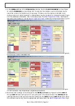
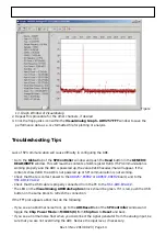
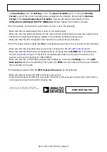
In the ADCBase 0 tab of the SPIController window, find the CLOCK DIVIDE(B) box (see Figure
3.
9), and the MODES(8) box (see Figure 10). If using the clock divider, use the drop-down box to
select the correct clock divide ratio, if necessary. If there is any interruption of the ADC clock
during power-up or during operation, a Digital Reset may be needed to re-initialize the ADC (Figure
10). For additional information, refer to the data sheet, the
, High Speed
ADC SPI Control Software, and the
, Interfacing to High Speed ADCs via SPI.
Figure 9.
SPI Controller, CLOCK DIVIDE(B) Box
Figure
10. SPI Controller, Chip Power Mode - Digital Reset Selection
Note that other settings can be changed on the ADCBase 0 tab (see Figure 9) and the ADC A
4.
through ADC H tabs (see Figure 11) to set up the part in the desired mode. The ADCBase 0 tab
settings affect the entire part, whereas the settings on the ADC A through ADC H tabs each affect
the selected channel only. See the appropriate part data sheet, the
, High

