UG-570
AD9361 Reference Manual
| Page 68 of 128
From a design flexibility viewpoint, the following Rx path
impedance matching strategy is preferred.
•
Place a differential matching network between the
balun/filter and the LNA input port.
•
Place a single-ended matching network on the balun/filter
input port.
The best matching network topology is application dependent.
The examples within this section are simpler narrow-band
cases. As the matching bandwidth increases, the required
number of matching sections increases.
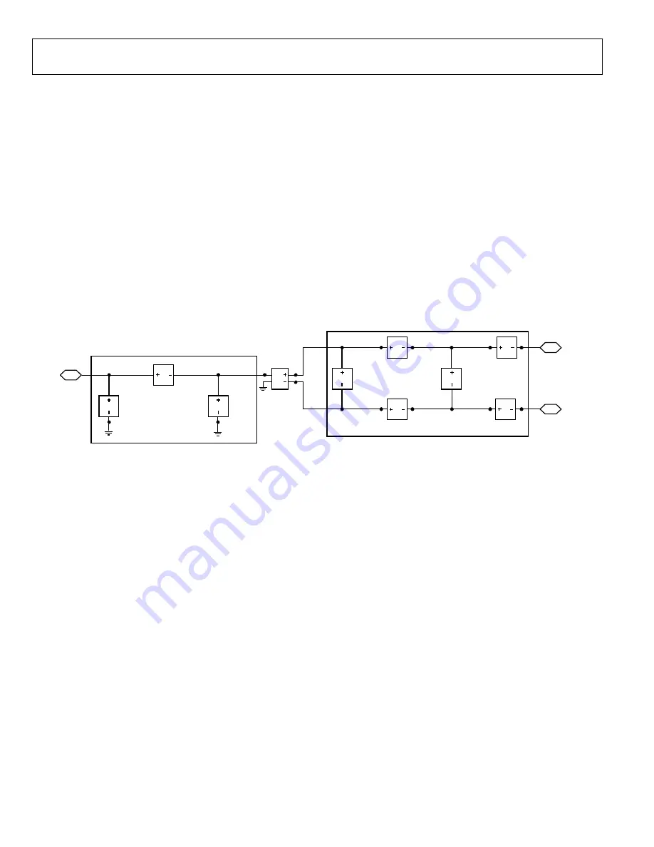
The LNA input ports have a DC voltage on them. A short to
ground at DC is to be avoided. Figure 48 defines the general
purpose matching topology.
The balun/filter single-ended port is impedance matched with a
simple PII network. The balun/filter differential port is
impedance matched with either a DC-blocked differential PII
network or a DC-blocked differential T network.
The DC-blocked differential T network is represented by the
smaller box in Figure 48. The DC-blocked differential PII
network is represented by the larger box in Figure 48.
The main advantages of the DC-blocked differential PII
network topology are a relatively wide impedance matching
bandwidth (up to 830 MHz) and Impedance Matching
Topology selection flexibility. The main disadvantage is a higher
number of SMD components.
The main advantage of the DC-blocked differential T network
topology is a lower SMD component count. The main
disadvantage is the impedance matching bandwidth may be up
to 5% smaller than the DC-blocked differential PII topology.
Figure 48.
AD9361
Rx Input General Purpose Impedance Matching Topology
DIFFERENTIAL MATCH
SINGLE-ENDED MATCH
S1P_EQN
S1P_EQN
S1P_EQN
S1P_EQN
S1P_EQN
S1P_EQN
S1P_EQN
S1P_EQN
S1P_EQN
BALUN3PORT
CMP1
S1P3
S1P1
S1P2
S1P4
S1P5
S1P6
S1P8
S1P9
S1P7
D
C
1
1668-
049
Rev. A


