Rev 20 Feb 2014 17:53 | Page 18
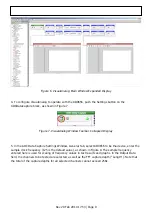
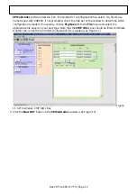
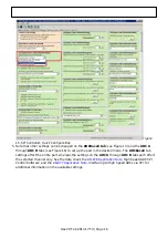
Figure
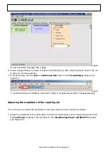
18. Graph Window of VisualAnalog
Repeat this procedure for the other channels, if desired
2.
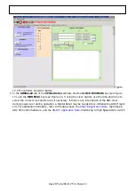
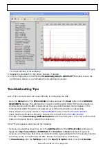
Click the floppy-disk icon within the VisualAnalog Graph - AD9656 FFT window to save the
3.
performance data as a .csv formatted file for plotting or analysis.
Troubleshooting Tips
Lack of SPI communication will cause difficulty in configuring the ADC.
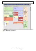
Go to the Global tab of the SPIController window and push the Read button in the GENERIC
●
READ/WRITE window. This will read the contents of ADC register 0x00. If SPI communication is
working properly and the ADC is powered up, the value 0x18 hexadecimal will appear. If the
contents show 0x00, the ADC is not powered up or SPI communication is not working.
Check that there is correct power to the
●
Check that the USB cable is properly connected from the PC to the
●
The LED on the VisualAnalog ADCDataCapture block should be green. If it is red, push the USB
●
button on the same block to refresh the connection.
If the FFT plot appears abnormal, do the following:
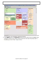
If you see an abnormal noise floor, go to the ADCBase0 tab of the SPIController window and
●
toggle the Chip Power Mode in MODES(8) from Chip Run to Reset and back (Figure 14).
If you see a normal noise floor when you disconnect the signal generator from the analog input, be
●
sure that you are not overdriving the ADC. Reduce the input level, if necessary.
In VisualAnalog, click the Settings icon in the Input Formatter block. Check that Number
●

