Rev 20 Feb 2014 17:53 | Page 6
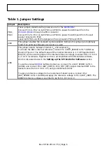
Table 1. Jumper Settings
Jumper
Description
P101,
P103
These jumpers determine the power source for the
Connect Pin 1 to Pin 2 on both P101 and P103 to power the ADC board from the
Connect Pin 2 to Pin 3 on both P101 and P103 to power the ADC board from the wall
supply connected to P102.
Leave both P101 and P103 unjumpered if using headers P104 and P105.
J304
This jumper enables the on-board crystal oscillator. Remove this jumper (and optimally
C302) if an external off-board clock source is used.
J206
This jumper selects between internal V
REF
and external V
REF
.
To choose the ADC's internal reference, connect Pin 3 (DUT_SENSE) to Pin 5 (GND) as
shown in Figure 2. The default value of the internal reference is 1 V. SPI Register 0x18
Bits[7:6] can be used to program the internal reference voltage to values from 1 V to 1.4
V, in 0.1 V increments. Register control is accomplished with SPIController software,
which is discussed below in the Setting up the SPI Controller Software section.
buffered reference, connect Pin 2 (DUT_SENSE) to Pin 1
(AVDD), and connect Pin 4 (DUT_VREF) to Pin 6 (EXT_REF). Adjust external VREF to the
desired value (from 1.0 V to 1.4 V) using potentiometer R247.
To apply a reference voltage from an external off-board source, connect Pin 2
(DUT_SENSE) to Pin 1 (AVDD) and apply the reference voltage to Pin 4 (DUT_VREF). The
AD9656 reference voltage is specified to be from 1.0 V to 1.4 V.

