AD9776A/AD9778A/AD9779A
Rev. B | Page 43 of 56
FULL-SCALE CURRENT GENERATION
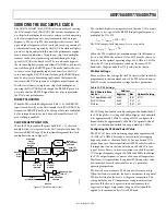
I DAC
DAC FULL-SCALE
REFERENCE
CURRENT
CURRENT
SCALING
I DAC GAIN
Q DAC GAIN
Q DAC
AD9776A/AD9778A/AD9779A
VREF
10k
Ω
1.2V BAND GAP
0.1µF
I120
06452
-073
INTERNAL REFERENCE
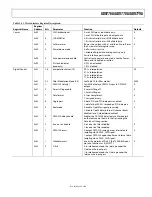
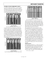
Full-scale current on the I DAC and Q DAC can be set from
8.66 mA to 31.66 mA. Initially, the 1.2 V band gap reference is
used to set up a current in an external resistor connected to I120
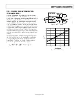
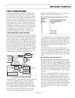
(Pin 75). A simplified block diagram of the reference circuitry is
shown in Figure 76. The recommended value for the external
resistor is 10 kΩ, which sets up an I
REFERENCE
in the resistor of
120 μA, which in turn provides a DAC output full-scale current
of 20 mA. Because the gain error is a linear function of this resistor,
a high precision resistor improves gain matching to the internal
matching specification of the devices. Gain drift over temperature
is also affected by this resistor. A resistor with a low temperature
coefficient is recommended in applications requiring good gain
stability.
Figure 76. Reference Circuitry
35
0
0
1000
DAC GAIN CODE
I
FS
(m
A
)
30
25
20
15
10
5
200
400
600
800
06
45
2-
07
4
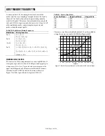
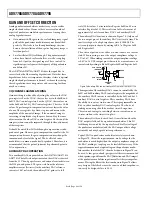
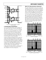
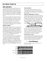
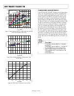
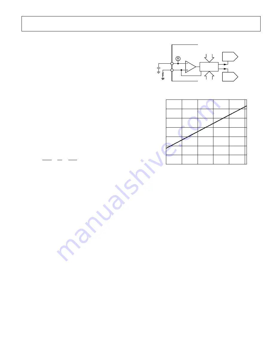
Internal current mirrors provide a current-gain scaling, where
the I DAC or Q DAC gain is a 10-bit word in the 3-wire interface
port register (Register 0x0B, Register 0x0C, Register 0x0F, and
Register 0x10). The default value for the DAC gain registers
gives an I
FS
of approximately 20 mA. I
FS
is equal to
32
1024
6
12
27
V
1.2
×
⎟
⎠
⎞
⎜
⎝
⎛
⎟
⎠
⎞
⎜
⎝
⎛
×
+
×
=
DAC Gain
R
I
FS
Figure 77. I
FS
vs. DAC Gain Code

