AD9776A/AD9778A/AD9779A
Rev. B | Page 7 of 56
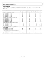
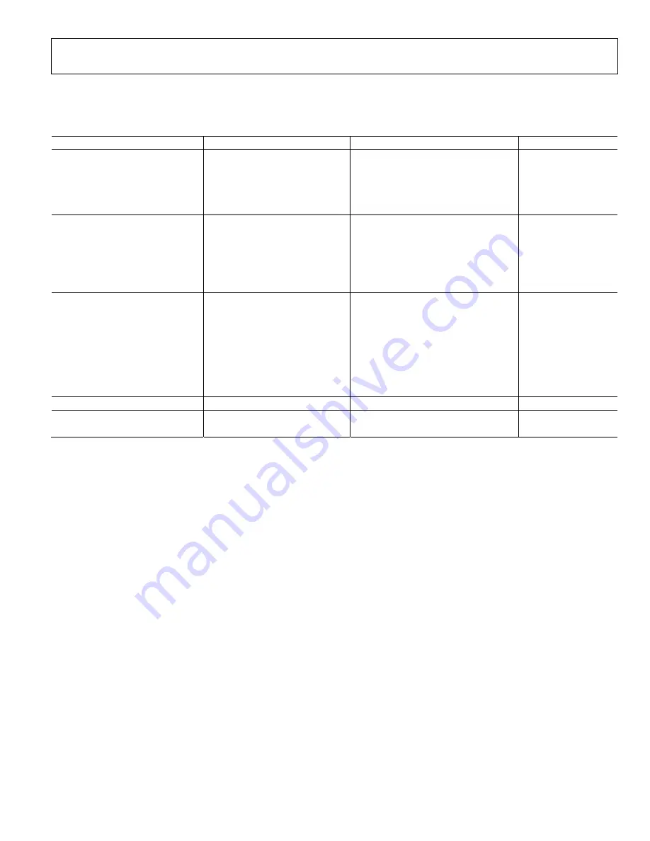
DIGITAL INPUT DATA TIMING SPECIFICATIONS
All modes, −40°C to +85°C.
Table 3.
Parameter Conditions
Min
Typ
Max
Unit
INPUT DATA
Setup Time
Input data to DATACLK
3.0
ns
Hold Time
Input data to DATACLK
−0.05
ns
Setup Time
Input data to REFCLK
−0.80
ns
Hold Time
Input data to REFCLK
3.80
ns
LATENCY
1× Interpolation
With or without modulation
25
DACCLK
cycles
2× Interpolation
With or without modulation
70
DACCLK
cycles
4× Interpolation
With or without modulation
146
DACCLK
cycles
8× Interpolation
With or without modulation
297
DACCLK
cycles
Inverse Sync
18
DACCLK cycles
3-WIRE INTERFACE
Maximum Clock Rate (SCLK)
40
MHz
Minimum Pulse Width High, t
PWH
12.5
ns
Minimum Pulse Width Low, t
PWL
12.5 ns
Setup Time, t
DS
SDIO to SCLK
2.8
ns
Hold Time, t
DH
SDIO to SCLK
0.0
ns
Setup Time, t
DS
CSB to SCLK
2.8
ns
Data Valid, t
DV
SDO to SCLK
2.0
ns
POWER-UP TIME
260
ms
RESET
Minimum Pulse Width, High
2
DACCLK cycles
1
Specified values are with PLL disabled. Timing vs. temperature and data valid keep out windows (that is, the minimum amount of time valid data must be presented to
the device to ensure proper sampling) are delineated in Table 28.
2
Measured from CSB rising edge when Register 0x00, Bit 4, is written from 1 to 0 with the VREF decoupling capacitor equal to 0.1 μF.


