ADM1060
Rev. B | Page 5 of 52
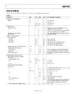
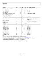
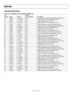
SPECIFICATIONS
(VH = 4.75 V to 14.4 V, VPn = 3.0 V to 6.0 V,
1
T
A
= −40°C to +85°C, unless otherwise noted.)
Table 1.
Parameter Min
Typ
Max
Unit
Test
Conditions/Comments
POWER SUPPLY ARBITRATION
VDDCAP
2.7
V
Any VPn ≥ 3.0 V
2.7
V
VH ≥ 4.75 V
4.75
5.1
V
Any VPn = 6.0 V
4.75
5.1
V
VH = 14.4 V
POWER SUPPLY
Supply Current, I
DD
3
mA
VDDCAP = 4.75 V, no PDO FET drivers on, no
loaded PDO pull-ups to VDDCAP
5
mA
VDDCAP = 4.75 V, all PDO FET drivers on (loaded
with 1 µA), no PDO pull-ups to VDDCAP
Additional Current Available
from
VDDCAP
2
1
mA
Max additional load that can be drawn from PDO
pull-ups to VDDCAP
SUPPLY FAULT DETECTORS
Input Impedance
VH Input
52
kΩ
From VH to GND
VPn
Inputs
52
kΩ
From
VPn
to
GND
VBn Inputs
190
kΩ
From VBn to 2.25 V (internal reference)
52
kΩ
From VBn to GND (positive mode)
30
kΩ
From VBn to GND (negative mode)
Absolute Accuracy (VH, VPn, VBn Inputs)
–2.5
+2.5
%
Calibrated Absolute Accuracy
3
VH, VPn Inputs
–1.0
+1.0
%
Factory preprogrammed to specific thresholds
VBn Inputs
–1.5
+1.5
%
Factory preprogrammed to specific thresholds
Glitch Filters (Digital)
0
100
µs
See Figure 19. Eight timeout options between 0 µs
and 100 µs
PROGRAMMABLE DRIVER OUTPUTS
High Voltage (Charge Pump) Mode
(PDOs 1 to 4)
Output
Impedance,
R
OUT
440
kΩ
V
OH
11
12.5
14
V
I
OH
= 0 µA
10.5
12
V
I
OH
= 1 µA
I
OUTAVG
20
µA
2
V
<
V
OH
< 7 V
Standard (Digital Output) Mode
(PDOs 1 to 9)
V
OH
2.4
V
V
PU
(pull-up to VDDCAP or VPn) > 2.7 V, I
OH
= 1 mA
4.5
V
V
PU
to VPn = 6.0 V, I
OH
= 0 mA
VPU – 0.3
V
V
PU
≤ 2.7 V, I
OH
= 1 mA
V
OL
0.4
V
I
OL
= 2 mA
1.2
V
I
OL
= 10 mA
2.0
V
I
OL
= 15 mA
I
SINK
2
20
mA
Total sink current (PDO1–PDO9)
R
PULLUP-
Weak Pull-Up
20
kΩ
Internal pull-up
I
SOURCE (VPn)
2
2
mA
Current load on any VPn pull-up (i.e., total source
current available through any number of PDO
pull-up switches configured on to any one)
Three-State Output Leakage Current
10
µA
V
PDO
= 14.4 V


