Connectors
3-6
ADSP-2181 EZ-KIT Lite Evaluation System Manual
• The
P2
and
P3
connectors are sites for 50-pin header connectors.
These connectors can be used to access the ADSP-2181 processor’s
signals for expansion or test purposes. For more information, see
“Expansion Port Connectors” on page 3-7
.
• The
U2
socket is a socket for an EPROM in a DIP package. As
built, the board accepts a 27C512 (64K byte) or 27C010 (128K
byte) EPROM. Changing connections at
JP1
allows the board to
accept a 27C256 (32K byte), 27C020 (256K byte), 27C040 (512K
byte), or 27C080 (1 Mbyte) EPROM. This socket is connected to
the ADSP-2181 processor’s byte-wide memory interface.
• The
R28
resistor is a site for a zero-ohm resistor. It this resistor is
installed the ADSP-2181 processor can reset the board under soft-
ware control. The software would assert reset by configuring the
PF0
flag as an output and then setting it low.
• The
R29
resistor is another site for a zero-ohm resistor. If this resis-
tor is installed and X3 and C37 are removed, the codec can operate
off of the ADSP-2181 processor’s
CLKOUT
signal instead of its own
24.576 MHz clock. It is also necessary to change
X1
to a lower fre-
quency value to stay within the codec’s ratings.
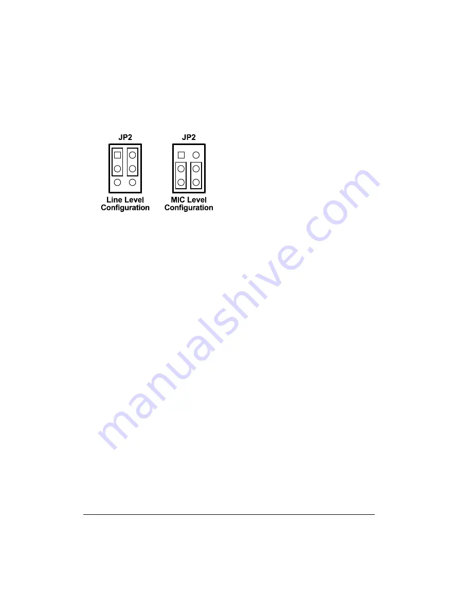
Figure 3-3. JP2 Jumper Settings
Summary of Contents for ADSP-2181
Page 42: ...Using EZ KIT Lite VisualDSP Interface 2 18 ADSP 2181 EZ KIT Lite Evaluation System Manual ...
Page 58: ...Designing EZ ICE Compatible Systems 3 16 ADSP 2181 EZ KIT Lite Evaluation System Manual ...
Page 60: ...A 2 ADSP 2181 EZ KIT Lite Evaluation System Manual ...
Page 64: ...B 4 ADSP 2181 EZ KIT Lite Evaluation System Manual ...
Page 70: ...INDEX I 6 ADSP 2181 EZ KIT Lite Evaluation System Manual ...

