


ADSP-2181 EZ-KIT Lite Evaluation System Manual
3-7
EZ-KIT Hardware Reference
Expansion Port Connectors
Two expansion port connectors (
P2
and
P3
) provide access to the
ADSP-2181 processor’s bus signals, letting you watch data transmissions.
The
P2
and
P3
connectors are sites for 50-pin header connectors. In addi-
tion, the host interface, interrupt, and
PWM_EVENT
pins are also available on
this connector
#
External port loading can effect external bus speed and
performance.
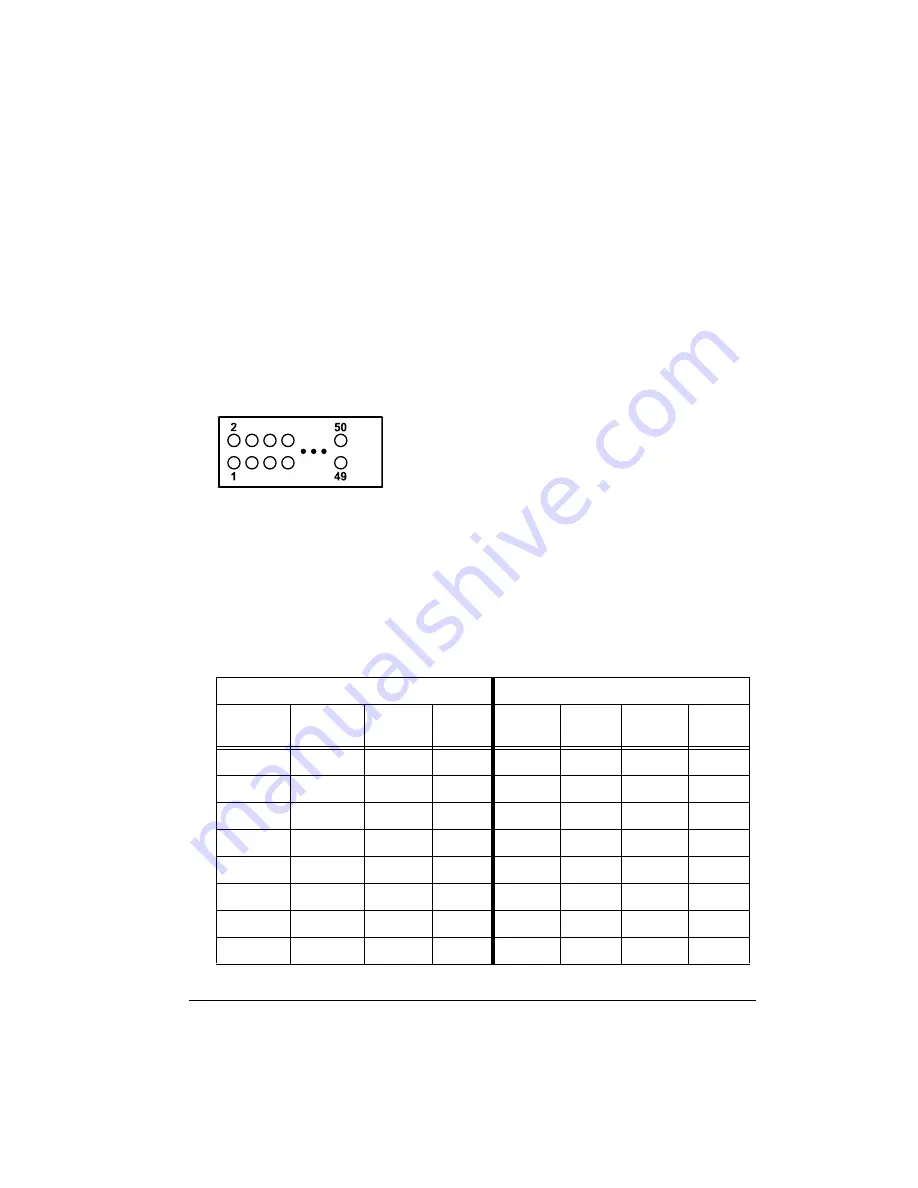
describes the signals available on the
P2
and
P3
pins.
Figure 3-4. Expansion Connector
Table 3-1. Expansion Connectors
P2
P3
Pin
Number
Signal
Name
Pin
Number
Signal
Name
Pin
Number
Signal
Name
Pin
Number
Signal
Name
1
A0
2
A1
1
GND
2
IAD0
3
A2
4
A3
3
IAD1
4
IAD2
5
A4
6
A5
5
IAD3
6
IAD4
7
A6
8
A7
7
IAD5
8
IAD6
9
A8
10
A9
9
IAD7
10
IAD8
11
A10
12
A11
11
IAD9
12
IAD10
13
A12
14
A13
13
IAD11
14
IAD12
15
D0
16
D1
15
IAD13
16
IAD14
Summary of Contents for ADSP-2181
Page 42: ...Using EZ KIT Lite VisualDSP Interface 2 18 ADSP 2181 EZ KIT Lite Evaluation System Manual ...
Page 58: ...Designing EZ ICE Compatible Systems 3 16 ADSP 2181 EZ KIT Lite Evaluation System Manual ...
Page 60: ...A 2 ADSP 2181 EZ KIT Lite Evaluation System Manual ...
Page 64: ...B 4 ADSP 2181 EZ KIT Lite Evaluation System Manual ...
Page 70: ...INDEX I 6 ADSP 2181 EZ KIT Lite Evaluation System Manual ...


