ADV7181B
Rev. B | Page 32 of 100
CG[11:0] Chroma Gain, Address 0x2D[3:0];
Address 0x2E[7:0]; CMG[11:0] Chroma Manual Gain,
Address 0x2D[3:0]; Address 0x2E[7:0]
Chroma gain[11:0] is a dual-function register. If written to, a
desired manual chroma gain can be programmed. This gain
becomes active if the CAGC[1:0] mode is switched to manual
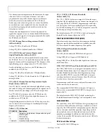
fixed gain. Refer to Equation 2 for calculating a desired gain.
If read back, this register returns the current gain value.
Depending on the setting in the CAGC[1:0] bits, this is either
•
Chroma manual gain value (CAGC[1:0] set to chroma
manual gain mode).
•
Chroma automatic gain value (CAGC[1:0] set to any of the
automatic modes).
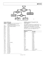
Table 40. CG/CMG Function
CG[11:0]/CMG[11:0] Read/Write Description
CMG[11:0] Write
Manual gain for chroma
path
CG[11:0] Read
Currently
active
gain
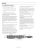
(
)
4
...
0
1024
4095
0
_
=
≤
<
=
CG
Gain
Chroma
(2)
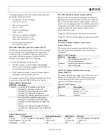
For example, freezing the automatic gain loop and reading back
the CG[11:0] register results in a value of 0x47A.
1.
Convert the readback value to decimal
0x47A = 1146d
2.
Apply Equation 2 to convert the readback value
1146/1024 = 1.12
CKE Color Kill Enable, Address 0x2B[6]
The color kill enable bit allows the optional color kill function
to be switched on or off.
For QAM-based video standards (PAL and NTSC) and FM-
based systems (SECAM), the threshold for the color kill
decision is selectable via the CKILLTHR[2:0] bits.
If color kill is enabled, and if the color carrier of the incoming
video signal is less than the threshold for 128 consecutive video
lines, color processing is switched off (black and white output).
To switch the color processing back on, another 128 consecutive
lines with a color burst greater than the threshold are required.
The color kill option works only for input signals with a
modulated chroma part. For component input (YPrPb), there is
no color kill.
Setting CKE to 0 disables color kill.
Setting CKE to 1 (default) enables color kill.
CKILLTHR[2:0] Color Kill Threshold,
Address 0x3D[6:4]
The CKILLTHR[2:0] bits allow the user to select a threshold for
the color kill function. The threshold applies to only QAM-
based (NTSC and PAL) or FM-modulated (SECAM) video
standards.
To enable the color kill function, the CKE bit must be set. For
settings 000, 001, 010, and 011, chroma demodulation inside
the ADV7181B may not work satisfactorily for poor input video
signals.
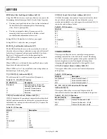
Table 41. CKILLTHR Function
Description
CKILLTHR[2:0]
SECAM NTSC,
PAL
000
No color kill
Kill at <0.5%
001
Kill at <5%
Kill at <1.5%
010
Kill at <7%
Kill at <2.5%
011
Kill at <8%
Kill at <4.0%
100 (default)
Kill at <9.5%
Kill at <8.5%
101
Kill at <15%
Kill at <16.0%
110
Kill at <32%
Kill at <32.0%
111
Reserved for ADI internal use only. Do not select.
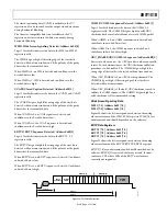
CHROMA TRANSIENT IMPROVEMENT (CTI)
The signal bandwidth allocated for chroma is typically much
smaller than that of luminance. In the past, this was a valid way
to fit a color video signal into a given overall bandwidth because
the human eye is less sensitive to chrominance than to
luminance.
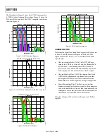
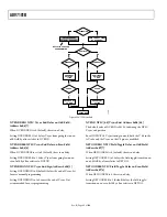
The uneven bandwidth, however, can lead to visual artifacts in
sharp color transitions. At the border of two bars of color, both
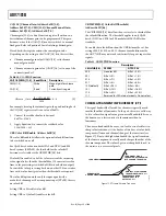
components (luma and chroma) change at the same time (see
Figure 17). Due to the higher bandwidth, the signal transition
of the luma component is usually much sharper than that of the
chroma component. The color edge is not sharp but blurred, in
the worst case, over several pixels.
LUMA SIGNAL
DEMODULATED
CHROMA SIGNAL
LUMA SIGNAL WITH A
TRANSITION, ACCOMPANIED
BY A CHROMA TRANSITION
ORIGINAL, SLOW CHROMA
TRANSITION PRIOR TO CTI
SHARPENED CHROMA
TRANSITION AT THE
OUTPUT OF CTI
04984-017
Figure 17. CTI Luma/Chroma Transition

