ADV7181B
Rev. B | Page 68 of 100
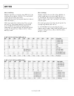
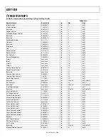
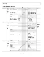
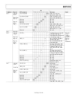
Table 84. Interrupt Register Map Details
Bit
Subaddress Register
Bit
Description
7 6 5 4 3 2 1 0
Comments
Notes
0
0 Open
drain
0
1
Drive low when active
1
0
Drive high when active
INTRQ_OP_SEL[1:0].
Interrupt Drive Level Select.
1
1
Reserved
0
Manual interrupt mode disabled
MPU_STIM_INTRQ[1:0].
Manual Interrupt Set Mode.
1
Manual
interrupt
mode
enabled
Reserved.
x
Not
used
0
0
Reserved
0
1
Pseudo
sync
only
1
0
Color
stripe
only
MV_INTRQ_SEL[1:0].
Macrovision Interrupt
Select.
1
1
Pseudo sync or color stripe
0
0
3 Xtal periods
0
1
15
Xtal
periods
1
0
63
Xtal
periods
0x40
Interrupt
Config 1
Register
Access
Page 2
INTRQ_DUR_SEL[1:0].
Interrupt Duration Select.
1
1
Active
until
cleared
0x41
Reserved
x x x x x x x x
0
No change
SD_LOCK_Q.
1
SD input has caused the decoder
to go from an unlocked state to
a locked state
0
No change
SD_UNLOCK_Q.
1
SD
input
has
caused
the
decoder to go from a locked
state to an unlocked state
Reserved.
x
Reserved.
x
Reserved.
x
0
No change
SD_FR_CHNG_Q.
1
Denotes
a
change
in
the
free-
run status
0
No change
MV_PS_CS_Q.
1
Pseudo sync/color striping
detected; see
MV_INTRQ_SEL[1:0],
Macrovision Interrupt
Selection Bits, Address 0x40
(Interrupt Space)[5:4]
for
selection
0x42 Interrupt
Status 1
Read Only
Register
Access
Page 2
Reserved.
x
These bits
can be
cleared or
masked in
Registers
0x43 and
0x44,
respectively.
0
Do not clear
SD_LOCK_CLR.
1 Clears
SD_LOCK_Q
bit
0
Do not clear
SD_UNLOCK_CLR.
1
Clears
SD_UNLOCK_Q
bit
Reserved.
0
Not used
Reserved.
0
Not
used
Reserved.
0
Not
used
0
Do not clear
SD_FR_CHNG_CLR.
1
Clears
SD_FR_CHNG_Q
bit
0
Do not clear
MV_PS_CS_CLR.
1
Clears
MV_PS_CS_Q
bit
0x43 Interrupt
Clear 1
Write Only
Register
Access
Page 2
Reserved.
x
Not used

