ADV7181B
Rev. B | Page 80 of 100
Bits
Subaddress
Register
Bit Description
7
6 5
4
3 2
1
0 Comments Notes
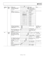
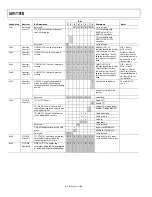
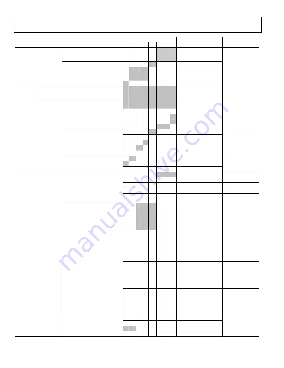
HSE[10:8]. HS end allows the
positioning of the HS output within
the video line.
0
0
0
HS output ends HSE[10:0]
pixels after the falling edge
of Hsync
Reserved.
0
Set to 0
HSB[10:8]. HS begin allows the
positioning of the HS output within
the video line.
0
0
0
HS output starts HSB[10:0]
pixels after the falling edge
of Hsync
0x34 HS
Position
Control 1
Reserved.
0
Set to 0
0x35 HS
Position
Control 2
HSB[7:0] Using HSB[10:0] and
HSE[10:0], the user can program the
position and length of HS output signal
.
0
0
0
0
0
0
1
0
0x36 HS
Position
Control 3
HSE[7:0] See Notes, above.
0
0
0
0
0
0
0
0
Using HSB and
HSE,the user can
program the
position and length
of the output Hsync.
0 Invert
polarity
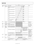
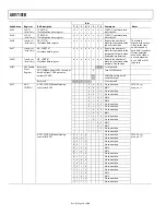
PCLK. Sets the polarity of LLC1.
1
Normal polarity as per the
timing diagrams
Reserved.
0
0
Set to 0
0 Active
high
PF. Sets the FIELD polarity.
1 Active
low
Reserved.
0
Set to 0
0 Active
high
PVS. Sets the VS Polarity.
1 Active
low
Reserved.
0 Set
to
0
0
Active
high
0x37 Polarity
PHS. Sets the HS Polarity.
1
Active
low
0
0
0
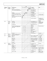
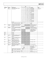
Adaptive 3-line, 3-tap luma
1
0
0
Use low-pass notch
1
0
1
Fixed luma comb (2-line)
Top lines of memory.
1
1
0
Fixed luma comb (3-Line)
All lines of memory.
YCMN[2:0]. Luma
comb mode, NTSC.
1
1
1
Fixed luma comb (2-line)
Bottom lines of
memory.
0
0
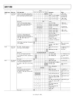
0 3-line adaptive for
CTAPSN = 01
4-line adaptive for
CTAPSN = 10
5-line adaptive for
CTAPSN = 11
1
0
0
Disable chroma comb
1 0
1 Fixed 2-line for
CTAPSN = 01
Fixed 3-line for
CTAPSN = 10
Fixed 4-line for
CTAPSN = 11
Top lines of
memory.
1 1
0 Fixed 3-line for
CTAPSN = 01
Fixed 4-line for
CTAPSN = 10
Fixed 5-line for
CTAPSN = 11
All lines of memory.
CCMN[2:0]. Chroma
comb mode, NTSC.
1 1
1 Fixed 2-line for
CTAPSN = 01
Fixed 3-line for
CTAPSN = 10
Fixed 4-line for
CTAPSN = 11
Bottom lines of
memory.
0
0
Adapts 3 lines – 2 lines
0
1
Not used
1
0
Adapts 5 lines – 3 lines
0x38 NTSC
Comb
Control
CTAPSN[1:0]. Chroma
comb taps, NTSC.
1
1
Adapts 5 lines – 4 lines


