ADV7181B
Rev. B | Page 30 of 100
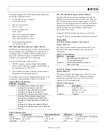
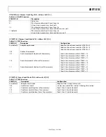
Table 32. AGC Modes
Input Video Type
Luma Gain
Chroma Gain
Any
Manual gain luma
Manual gain chroma
Dependent on color burst amplitude;
Dependent on horizontal sync depth
taken from luma path
Dependent on color burst amplitude;
CVBS
Peak white
taken from luma path
Dependent on color burst amplitude;
Dependent on horizontal sync depth
taken from luma path
Dependent on color burst amplitude;
Y/C
Peak white
taken from luma path
YPrPb
Dependent on horizontal sync depth
Taken from luma path
Luma Gain
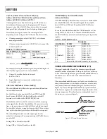
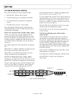
LAGC[2:0] Luma Automatic Gain Control,
Address 0x2C[7:0]
The luma automatic gain control mode bits select the mode of
operation for the gain control in the luma path.
There are ADI internal parameters to customize the peak white
gain control. Contact ADI sales for more information.
Table 33. LAGC Function
LAGC[2:0] Description
000
Manual fixed gain (use LMG[11:0])
001
AGC (blank level to sync tip); peak white
algorithm off
010 (default)
AGC (blank level to sync tip); peak white
algorithm on
011 Reserved
100 Reserved
101 Reserved
110 Reserved
111 Freeze
gain
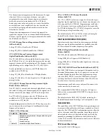
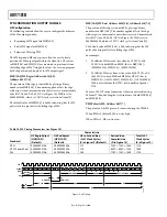
LAGT[1:0] Luma Automatic Gain Timing,
Address 0x2F[7:6]
The luma automatic gain timing register allows the user to
influence the tracking speed of the luminance automatic gain
control. This register only has an effect if the LAGC[2:0]
register is set to 001, 010, 011, or 100 (automatic gain control
modes).
If peak white AGC is enabled and active (see the
STATUS_1[7:0] Address 0x10[7:0] section), the actual gain
update speed is dictated by the peak white AGC loop and, as a
result, the LAGT settings have no effect. As soon as the part
leaves peak white AGC, LAGT becomes relevant again.
The update speed for the peak white algorithm can be
customized by the use of internal parameters. Contact ADI
sales for more information.
Table 34. LAGT Function
LAGT[1:0] Description
00
Slow (TC = 2 sec)
01
Medium (TC = 1 sec)
10
Fast (TC = 0.2 sec)
11 (default)
Adaptive
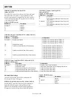
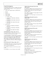
LG[11:0] Luma Gain, Address 0x2F[3:0];
Address 0x30[7:0]; LMG[11:0] Luma Manual Gain,
Address 0x2F[3:0]; Address 0x30[7:0]
Luma gain[11:0] is a dual-function register. If written to, a
desired manual luma gain can be programmed. This gain
becomes active if the LAGC[2:0] mode is switched to manual
fixed gain. Equation 1 shows how to calculate a desired gain.
If read back, this register returns the current gain value.
Depending on the setting in the LAGC[2:0] bits, one of these
gain values is returned:
•
Luma manual gain value (LAGC[2:0] set to luma manual
gain mode)
•
Luma automatic gain value (LAGC[2:0] set to any of the
automatic modes)
Table 35. LG/LMG Function
LG[11:0]/LMG[11:0] Read/Write Description
LMG[11:0] = X
Write
Manual gain for luma
path
LG[11:0]
Read
Actually used gain
(
)
2
...
0
2048
4095
0
_
=
≤
<
=
LG
Gain
Luma
(1)

