ADV7181B
Rev. B | Page 50 of 100
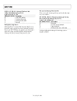
LB_LCT[7:0] Letterbox Line Count Top,
Address 0x9B[7:0]; LB_LCM[7:0] Letterbox Line Count
Mid, Address 0x9C[7:0]; LB_LCB[7:0] Letterbox Line Count
Bottom, Address 0x9D[7:0]
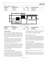
Table 61. LB_LCx Access Information
Signal Name
Address
Register Default Value
LB_LCT[7:0] 0x9B Readback
only
LB_LCM[7:0] 0x9C
Readback
only
LB_LCB[7:0] 0x9D Readback
only
LB_TH[4:0] Letterbox Threshold Control,
Address 0xDC[4:0]
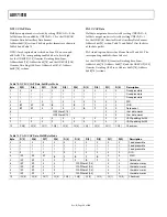
Table 62. LB_TH Function
LB_TH[4:0] Description
01100 (default)
Default threshold for detection of black lines
01101 to
10000
Increase threshold (need larger active video
content before identifying non-black lines)
00000 to
01011
Decrease threshold (even small noise levels
can cause the detection of non-black lines)
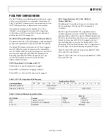
LB_SL[3:0] Letterbox Start Line, Address 0xDD[7:4]
The LB_SL[3:0] bits are set at 0100b by default. This means the
letterbox detection window starts after the EDTV VBI data line.
For an NTSC signal, this window is from Line 23 to Line 286.
Changing the bits to 0101, the detection window starts on
Line 24 and ends on Line 287.
LB_EL[3:0] Letterbox End Line, Address 0xDD[3:0]
The LB_EL[3:0] bits are set at 1101b by default. This means that
letterbox detection window ends with the last active video line.
For an NTSC signal, this window is from Line 262 to Line 525.
Changing the bits to 1100, the detection window starts on
Line 261 and ends on Line 254.
Gemstar Data Recovery
The Gemstar-compatible data recovery block (GSCD) supports
1× and 2× data transmissions. In addition, it can also serve as a
closed caption decoder. Gemstar-compatible data transmissions
can only occur in NTSC. Closed caption data can be decoded in
both PAL and NTSC.
The block is configured via I
2
C in the following ways:
•
GDECEL[15:0] allows data recovery on selected video lines
on even fields to be enabled and disabled.
•
GDECOL[15:0] enables the data recovery on selected lines
for odd fields.
•
GDECAD configures the way in which data is embedded
in the video data stream.
The recovered data is not available through I
2
C, but is inserted
into the horizontal blanking period of an ITU-R BT.656-com-
patible data stream. The data format is intended to comply with
the recommendation by the International Telecommunications
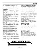
Union, ITU-R BT.1364. See Figure 34. For more information,
see the ITU website at www.itu.ch.
The format of the data packet depends on the following criteria:
•
Transmission is 1× or 2×.
•
Data is output in 8-bit or 4-bit format (see the GDECAD
Gemstar Decode Ancillary Data Format,
Address 0x4C[0] section).
•
Data is closed caption (CCAP) or Gemstar-compatible.
Data packets are output if the corresponding enable bit is set
(see the GDECEL[15:0] Gemstar Decoding Even Lines,
Address 0x48[7:0]; Address 0x49[7:0] and GDECOL[15:0]
Gemstar Decoding Odd Lines, Address 0x4A[7:0]; Address
0x4B[7:0] sections), and if the decoder detects the presence of
data. This means that for video lines where no data has been
decoded, no data packet is output even if the corresponding line
enable bit is set.
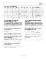
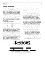
Each data packet starts immediately after the EAV code of the
preceding line. Figure 34 and Table 63 show the overall
structure of the data packet.
Entries within the packet are as follows:
•
Fixed preamble sequence of 0x00, 0xFF, 0xFF.
•
Data identification word (DID). The value for the DID
marking a Gemstar or CCAP data packet is 0x140
(10-bit value).
•
Secondary data identification word (SDID) contains
information about the video line from which data was
retrieved, whether the Gemstar transmission was of 1× or
2× format, and whether it was retrieved from an even or
odd field.
•
Data count byte, giving the number of user data-words that
follow.
•
User data section.
•
Optional padding to ensure the length of the user data-
word section of a packet is a multiple of four bytes,
requirement as set in ITU-R BT.1364.
•
Checksum byte.
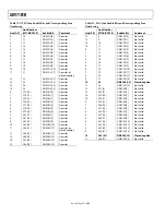
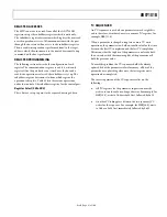
Table 63 lists the values within a generic data packet that are
output by the ADV7181B in 8-bit format. In 8-bit systems,
Bits D1 and D0 in the data packets are disregarded.

