ADV8003 Hardware Manual
Rev. B, August 2013
210
Video Input 1
CSC
OSD
Blend
OSD
Core
SPI Master/
Slave
Microcontroller/
Flash
DDR2
Memory
OSD
Scaler
Video Input 1
CSC
OSD
Blend
OSD
Core
SPI Master/
Slave
Microcontroller/
Flash
DDR2
Memory
OSD
Scaler
Video Input 2
Video Input 2
Blended Output 1
Blended Output 1
Blended Output 2
Blended Output 2
OSD
Core
External
OSD
OSD
Core
Internally
Generated
OSD
OSD TTL Input
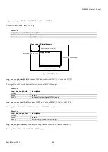
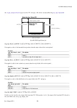
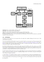
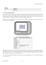
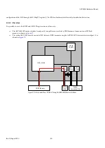
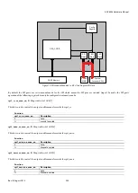
Figure 73: Bitmap OSD Top Level Diagram
OSD Blend:
Used to overlay the OSD data with the input video.
OSD Scaler:
Used to scale the OSD to the target resolution.
CSC:
Used to convert the OSD core data color to the same color space as that of the input video.
OSD Core:
Used to generate internal OSD data. Reads data from DDR2 memory and outputs data to FIFO.
SPI Master and SPI Slave:
SPI master used to copy flash data into DDR2 memory. SPI slave used as the only means to control OSD
configuration registers and memories.
4.2.3.
OSD Blending
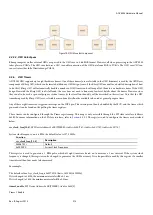
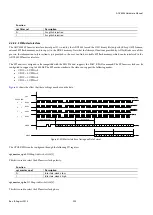
The OSD core in the ADV8003 has two video inputs and two video outputs and is capable of blending at data rates of up to 3 GHz
(ADV8003KBCZ-8x derivatives).
The two video inputs allow two different video streams to be connected to the OSD core, for example, video TTL input channel and SVSP
output. The inputs connected to the OSD core can be selected using
and
. Refer to
for further details.
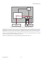
The video stream connected to OSD input 1 is output to the OSD blend 1 output and the video stream
connected to OSD input 2 is output to the OSD blend 2 output.
The OSD can be blended onto either one of the two video streams connected to the OSD core, that is, there is only one source of OSD
data and it must be configured to match one video stream’s format and timing at a time. The OSD can be switched between the two video
streams without causing any disturbance on either output video stream. The OSD core outputs can be connected to one or more of the
output blocks, for example, HDMI TX1, HDMI TX2, SD encoder and HD encoder.
The OSD is blended with the selected video stream using alpha blending. This means that each pixel of OSD has its own blending
parameter which is used to blend this pixel with its corresponding background video. If the OSD data is transparent, the background
video will be passed through and unadjusted.
As shown in
, the OSD data needs to be scaled to the target resolution before getting into the blending block (refer to
Section
4.2.7). The clock and DE of the selected video stream are used to read the scaler output data. Delay is added to DATA, DE, HS and
VS for matching the delay of the OSD processing, so the OSD scaler can ensure the correct synchronization of OSD data and input video
Summary of Contents for ADV8003
Page 366: ...ADV8003 Hardware Manual Rev B August 2013 366 Figure 144 ADV8003 Schematic Page 4...
Page 367: ...ADV8003 Hardware Manual Rev B August 2013 367 Figure 145 ADV8003 Schematic Page 5...
Page 368: ...ADV8003 Hardware Manual Rev B August 2013 368 Figure 146 ADV8003 Schematic Page 6...
Page 369: ...ADV8003 Hardware Manual Rev B August 2013 369 Figure 147 ADV8003 Schematic Page 7...
Page 371: ...ADV8003 Hardware Manual Rev B August 2013 371 Figure 149 ADV8003 Schematic Page 9...
Page 372: ...ADV8003 Hardware Manual Rev B August 2013 372 Figure 150 ADV8003 Schematic Page 10...
Page 373: ...ADV8003 Hardware Manual Rev B August 2013 373 Figure 151 ADV8003 Schematic Page 11...
Page 374: ...ADV8003 Hardware Manual Rev B August 2013 374 Figure 152 ADV8003 Schematic Page 12...
Page 375: ...ADV8003 Hardware Manual Rev B August 2013 375 Figure 153 ADV8003 Schematic Page 13...
Page 376: ...ADV8003 Hardware Manual Rev B August 2013 376 Figure 154 ADV8003 Schematic Page 14...
Page 377: ...ADV8003 Hardware Manual Rev B August 2013 377 Figure 155 ADV8003 Schematic Page 15...
Page 378: ...ADV8003 Hardware Manual Rev B August 2013 378 Figure 156 ADV8003 Schematic Page 16...
Page 379: ...ADV8003 Hardware Manual Rev B August 2013 379 Figure 157 ADV8003 Schematic Page 17...
Page 380: ...ADV8003 Hardware Manual Rev B August 2013 380 Figure 158 ADV8003 Schematic Page 18...
Page 381: ...ADV8003 Hardware Manual Rev B August 2013 381 Figure 159 ADV8003 Schematic Page 19...
Page 382: ...ADV8003 Hardware Manual Rev B August 2013 382 Figure 160 ADV8003 Schematic Page 20...
Page 383: ...ADV8003 Hardware Manual Rev B August 2013 383 Figure 161 ADV8003 Schematic Page 21...
Page 384: ...ADV8003 Hardware Manual Rev B August 2013 384 Figure 162 ADV8003 Schematic Page 22...
Page 385: ...ADV8003 Hardware Manual Rev B August 2013 385 Figure 163 ADV8003 Schematic Page 23...
Page 386: ...ADV8003 Hardware Manual Rev B August 2013 386 Figure 164 ADV8003 Schematic Page 24...
Page 387: ...ADV8003 Hardware Manual Rev B August 2013 387 Figure 165 ADV8003 Schematic Page 25...
Page 388: ...ADV8003 Hardware Manual Rev B August 2013 388 Figure 166 ADV8003 Schematic Page 26...
Page 389: ...ADV8003 Hardware Manual Rev B August 2013 389 Figure 167 ADV8003 Schematic Page 27...
Page 390: ...ADV8003 Hardware Manual Rev B August 2013 390 Figure 168 ADV8003 Schematic Page 28...
Page 391: ...ADV8003 Hardware Manual Rev B August 2013 391 Figure 169 ADV8003 Schematic Page 29...
Page 392: ...ADV8003 Hardware Manual Rev B August 2013 392 Figure 170 ADV8003 Schematic Page 30...
Page 393: ...ADV8003 Hardware Manual Rev B August 2013 393 Figure 171 ADV8003 Schematic Page 31...
Page 395: ...ADV8003 Hardware Manual Rev B August 2013 395 Figure 173 ADV8003 Layout Page 2...
Page 396: ...ADV8003 Hardware Manual Rev B August 2013 396 Figure 174 ADV8003 Layout Page 3...
Page 397: ...ADV8003 Hardware Manual Rev B August 2013 397 Figure 175 ADV8003 Layout Page 4...
Page 398: ...ADV8003 Hardware Manual Rev B August 2013 398 Figure 176 ADV8003 Layout Page 5...
Page 399: ...ADV8003 Hardware Manual Rev B August 2013 399 Figure 177 ADV8003 Layout Page 6...
Page 400: ...ADV8003 Hardware Manual Rev B August 2013 400 Figure 178 ADV8003 Layout Page 7...
Page 401: ...ADV8003 Hardware Manual Rev B August 2013 401 Figure 179 ADV8003 Layout Page 8...
Page 427: ...ADV8003 Hardware Manual Rev B August 2013 427 P 2 Z Z Z P 1 Z Z Z P 0 Z Z Z...

