ADV8003 Hardware Manual
Rev. B, August 2013
301
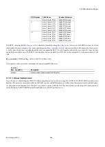
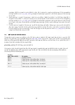
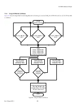
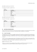
timestamp of 0b10 is assigned to receive buffer 0 to show that it contains the second received message. If the corresponding
interrupt mask bit is set,
goes high and an interrupt is generated to alert the host processor that a message
was received.
6.
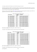
Another message is received. This message is stored in receive buffer 2 (buffer 0 and buffer 1 are full). Time stamp 0b11 is
assigned to receive buffer 2 to show that it contains an unread message that was the third to be received. If the corresponding
interrupt mask bit is set,
goes high and an interrupt is generated to alert the host processor that a message
was received. At this time all receive buffers are full and no more messages can be received until the processor reads at least one
message.
7.
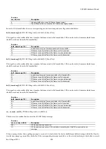
The host processor responds to the interrupts, or polls the timestamps and realizes that messages were received, and reads the
three time stamps. The buffer with the earliest time stamp should be read first. Therefore, receive buffer 1 is read first, followed
by receive buffer 0 and then receive buffer 2. Once the messages are read the processor clears
. The time
stamps for all three buffers are reset to 0b00.
7.4.
ANTIGLITCH FILTER MODULE
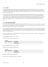
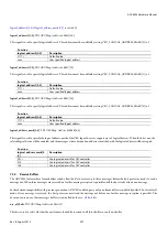
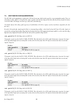
This module is used to remove any glitches on the CEC bus in order to make the CEC input signal cleaner before it enters the CEC
module. The glitch filter is programmable through the
register. The register value specifies the minimum pulse
width that will be passed through by the module. Any pulses with narrower widths are rejected. There is a cec_glitch_filte 1
number of clock delays introduced by the antiglitch filter.
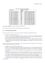
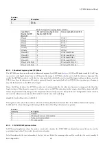
glitch_filter_ctrl[5:0]
, TX2 CEC Map,
Address 0xF84F[5:0]
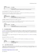
This signal is used to control the glitch filter. The CEC input signal is sampled by the input clock (XTAL clock). cec_glitch_filter_ctrl
specifies the minimum pulse width requirement in input clock cycles. Pulses of widths less than the minimum specified width are
considered glitches and will be removed.
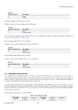
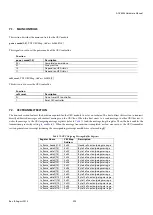
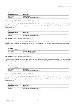
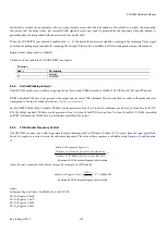
Function
glitch_filter_ctrl[5:0]
Description
000000
Disable glitch filter
000001
Filter out pulses with width less than 1 clock cycle
000010
Filter out pulses with width less than 2 clock cycles
...
000111
Filter out pulses with width less than 7 clock cycles
...
111111
Filter out pulses with width less than 63 clock cycles
Summary of Contents for ADV8003
Page 366: ...ADV8003 Hardware Manual Rev B August 2013 366 Figure 144 ADV8003 Schematic Page 4...
Page 367: ...ADV8003 Hardware Manual Rev B August 2013 367 Figure 145 ADV8003 Schematic Page 5...
Page 368: ...ADV8003 Hardware Manual Rev B August 2013 368 Figure 146 ADV8003 Schematic Page 6...
Page 369: ...ADV8003 Hardware Manual Rev B August 2013 369 Figure 147 ADV8003 Schematic Page 7...
Page 371: ...ADV8003 Hardware Manual Rev B August 2013 371 Figure 149 ADV8003 Schematic Page 9...
Page 372: ...ADV8003 Hardware Manual Rev B August 2013 372 Figure 150 ADV8003 Schematic Page 10...
Page 373: ...ADV8003 Hardware Manual Rev B August 2013 373 Figure 151 ADV8003 Schematic Page 11...
Page 374: ...ADV8003 Hardware Manual Rev B August 2013 374 Figure 152 ADV8003 Schematic Page 12...
Page 375: ...ADV8003 Hardware Manual Rev B August 2013 375 Figure 153 ADV8003 Schematic Page 13...
Page 376: ...ADV8003 Hardware Manual Rev B August 2013 376 Figure 154 ADV8003 Schematic Page 14...
Page 377: ...ADV8003 Hardware Manual Rev B August 2013 377 Figure 155 ADV8003 Schematic Page 15...
Page 378: ...ADV8003 Hardware Manual Rev B August 2013 378 Figure 156 ADV8003 Schematic Page 16...
Page 379: ...ADV8003 Hardware Manual Rev B August 2013 379 Figure 157 ADV8003 Schematic Page 17...
Page 380: ...ADV8003 Hardware Manual Rev B August 2013 380 Figure 158 ADV8003 Schematic Page 18...
Page 381: ...ADV8003 Hardware Manual Rev B August 2013 381 Figure 159 ADV8003 Schematic Page 19...
Page 382: ...ADV8003 Hardware Manual Rev B August 2013 382 Figure 160 ADV8003 Schematic Page 20...
Page 383: ...ADV8003 Hardware Manual Rev B August 2013 383 Figure 161 ADV8003 Schematic Page 21...
Page 384: ...ADV8003 Hardware Manual Rev B August 2013 384 Figure 162 ADV8003 Schematic Page 22...
Page 385: ...ADV8003 Hardware Manual Rev B August 2013 385 Figure 163 ADV8003 Schematic Page 23...
Page 386: ...ADV8003 Hardware Manual Rev B August 2013 386 Figure 164 ADV8003 Schematic Page 24...
Page 387: ...ADV8003 Hardware Manual Rev B August 2013 387 Figure 165 ADV8003 Schematic Page 25...
Page 388: ...ADV8003 Hardware Manual Rev B August 2013 388 Figure 166 ADV8003 Schematic Page 26...
Page 389: ...ADV8003 Hardware Manual Rev B August 2013 389 Figure 167 ADV8003 Schematic Page 27...
Page 390: ...ADV8003 Hardware Manual Rev B August 2013 390 Figure 168 ADV8003 Schematic Page 28...
Page 391: ...ADV8003 Hardware Manual Rev B August 2013 391 Figure 169 ADV8003 Schematic Page 29...
Page 392: ...ADV8003 Hardware Manual Rev B August 2013 392 Figure 170 ADV8003 Schematic Page 30...
Page 393: ...ADV8003 Hardware Manual Rev B August 2013 393 Figure 171 ADV8003 Schematic Page 31...
Page 395: ...ADV8003 Hardware Manual Rev B August 2013 395 Figure 173 ADV8003 Layout Page 2...
Page 396: ...ADV8003 Hardware Manual Rev B August 2013 396 Figure 174 ADV8003 Layout Page 3...
Page 397: ...ADV8003 Hardware Manual Rev B August 2013 397 Figure 175 ADV8003 Layout Page 4...
Page 398: ...ADV8003 Hardware Manual Rev B August 2013 398 Figure 176 ADV8003 Layout Page 5...
Page 399: ...ADV8003 Hardware Manual Rev B August 2013 399 Figure 177 ADV8003 Layout Page 6...
Page 400: ...ADV8003 Hardware Manual Rev B August 2013 400 Figure 178 ADV8003 Layout Page 7...
Page 401: ...ADV8003 Hardware Manual Rev B August 2013 401 Figure 179 ADV8003 Layout Page 8...
Page 427: ...ADV8003 Hardware Manual Rev B August 2013 427 P 2 Z Z Z P 1 Z Z Z P 0 Z Z Z...

