ADV8003 Hardware Manual
Rev. B, August 2013
313
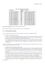
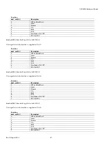
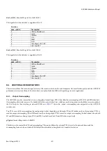
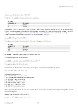
Function
pll_pdn
Description
0
PLL on
1
PLL off
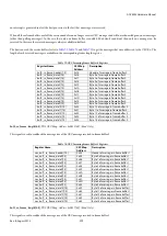
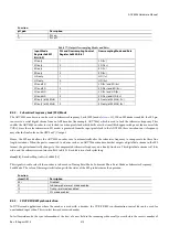
Table 77: Output Oversampling Modes and Rates
Input Mode
Register 0xE401,
Bits[6:4]
PLL and Oversampling Control
Register 0xE400, Bit 1
Oversampling Mode and Rate
SD only
1
SD (2×)
SD only
0
SD (16×)
ED only
1
ED (1×)
ED only
0
ED (8×)
HD only
1
HD (1×)
HD only
0
HD (4×)
SD and ED
1
SD (2×) and ED (8×)
SD and ED
0
SD (16×) and ED (8×)
SD and HD
1
SD (2×) and HD (4×)
SD and HD
0
SD (16×) and HD (4×)
ED only (at 54 MHz)
1
ED only (at 54 MHz) (1×)
ED only (at 54 MHz)
0
ED only (at 54 MHz) (8×)
8.4.2.
Subcarrier Frequency Lock (SFL) Mode
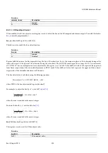
The ADV8003 encoder core can be used in Subcarrier Frequency Lock (SFL) mode (
rtcen
= 11). When SFL mode is enabled, the SFL pin
can receive a serial digital stream from an ADI decoder (for example, ADV784x) which is used to lock the subcarrier frequency. This
enables the ADV8003 encoder to stay locked to a video pixel clock which drifts over the time (this happens with poor video sources like
VCRs). Since the color subcarrier in SD modes is generated from the input pixel clock to the ADV8003, these variations on its frequency
may alter the final color on the CBVS or Y/C output.
Hence, the SFL mode allows the ADV8003 encoder core to automatically alter the subcarrier frequency to compensate for these line
length variations. When the part is connected to a device such as an ADV784x video decoder that outputs a digital data stream in the SFL
format, the part automatically changes to the compensated subcarrier frequency on a line-by-line basis. This digital data stream is 67-bits
wide, and the subcarrier is contained in Bit 0 to Bit 21. Each bit is two clock cycles long.
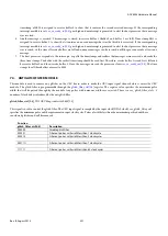
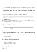
rtcen[1:0]
, Encoder Map,
Address 0xE484[2:1]
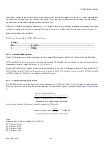
This signal is used to select if the encoder is to be used in Timing Reset Mode, Subcarrier Phase Reset Mode or Subcarrier Frequency
Lock Mode. The value of these register bits along with the status of the SFL pin determine the operation.
Function
rtcen[1:0]
Description
00
Disabled
01
Subcarrier phase reset mode enabled
10
Timing reset mode enabled
11
SFL mode enabled
8.4.3.
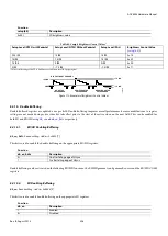
SD VCR FF/RW Synchronization
In DVD record applications where the encoder is used with a decoder, the VCR FF/RW synchronization control bit can be used for
nonstandard input video. This is in fast forward or rewind modes.
In fast forward mode, the sync information at the start of a new field in the incoming video usually occurs before the correct number of
Summary of Contents for ADV8003
Page 366: ...ADV8003 Hardware Manual Rev B August 2013 366 Figure 144 ADV8003 Schematic Page 4...
Page 367: ...ADV8003 Hardware Manual Rev B August 2013 367 Figure 145 ADV8003 Schematic Page 5...
Page 368: ...ADV8003 Hardware Manual Rev B August 2013 368 Figure 146 ADV8003 Schematic Page 6...
Page 369: ...ADV8003 Hardware Manual Rev B August 2013 369 Figure 147 ADV8003 Schematic Page 7...
Page 371: ...ADV8003 Hardware Manual Rev B August 2013 371 Figure 149 ADV8003 Schematic Page 9...
Page 372: ...ADV8003 Hardware Manual Rev B August 2013 372 Figure 150 ADV8003 Schematic Page 10...
Page 373: ...ADV8003 Hardware Manual Rev B August 2013 373 Figure 151 ADV8003 Schematic Page 11...
Page 374: ...ADV8003 Hardware Manual Rev B August 2013 374 Figure 152 ADV8003 Schematic Page 12...
Page 375: ...ADV8003 Hardware Manual Rev B August 2013 375 Figure 153 ADV8003 Schematic Page 13...
Page 376: ...ADV8003 Hardware Manual Rev B August 2013 376 Figure 154 ADV8003 Schematic Page 14...
Page 377: ...ADV8003 Hardware Manual Rev B August 2013 377 Figure 155 ADV8003 Schematic Page 15...
Page 378: ...ADV8003 Hardware Manual Rev B August 2013 378 Figure 156 ADV8003 Schematic Page 16...
Page 379: ...ADV8003 Hardware Manual Rev B August 2013 379 Figure 157 ADV8003 Schematic Page 17...
Page 380: ...ADV8003 Hardware Manual Rev B August 2013 380 Figure 158 ADV8003 Schematic Page 18...
Page 381: ...ADV8003 Hardware Manual Rev B August 2013 381 Figure 159 ADV8003 Schematic Page 19...
Page 382: ...ADV8003 Hardware Manual Rev B August 2013 382 Figure 160 ADV8003 Schematic Page 20...
Page 383: ...ADV8003 Hardware Manual Rev B August 2013 383 Figure 161 ADV8003 Schematic Page 21...
Page 384: ...ADV8003 Hardware Manual Rev B August 2013 384 Figure 162 ADV8003 Schematic Page 22...
Page 385: ...ADV8003 Hardware Manual Rev B August 2013 385 Figure 163 ADV8003 Schematic Page 23...
Page 386: ...ADV8003 Hardware Manual Rev B August 2013 386 Figure 164 ADV8003 Schematic Page 24...
Page 387: ...ADV8003 Hardware Manual Rev B August 2013 387 Figure 165 ADV8003 Schematic Page 25...
Page 388: ...ADV8003 Hardware Manual Rev B August 2013 388 Figure 166 ADV8003 Schematic Page 26...
Page 389: ...ADV8003 Hardware Manual Rev B August 2013 389 Figure 167 ADV8003 Schematic Page 27...
Page 390: ...ADV8003 Hardware Manual Rev B August 2013 390 Figure 168 ADV8003 Schematic Page 28...
Page 391: ...ADV8003 Hardware Manual Rev B August 2013 391 Figure 169 ADV8003 Schematic Page 29...
Page 392: ...ADV8003 Hardware Manual Rev B August 2013 392 Figure 170 ADV8003 Schematic Page 30...
Page 393: ...ADV8003 Hardware Manual Rev B August 2013 393 Figure 171 ADV8003 Schematic Page 31...
Page 395: ...ADV8003 Hardware Manual Rev B August 2013 395 Figure 173 ADV8003 Layout Page 2...
Page 396: ...ADV8003 Hardware Manual Rev B August 2013 396 Figure 174 ADV8003 Layout Page 3...
Page 397: ...ADV8003 Hardware Manual Rev B August 2013 397 Figure 175 ADV8003 Layout Page 4...
Page 398: ...ADV8003 Hardware Manual Rev B August 2013 398 Figure 176 ADV8003 Layout Page 5...
Page 399: ...ADV8003 Hardware Manual Rev B August 2013 399 Figure 177 ADV8003 Layout Page 6...
Page 400: ...ADV8003 Hardware Manual Rev B August 2013 400 Figure 178 ADV8003 Layout Page 7...
Page 401: ...ADV8003 Hardware Manual Rev B August 2013 401 Figure 179 ADV8003 Layout Page 8...
Page 427: ...ADV8003 Hardware Manual Rev B August 2013 427 P 2 Z Z Z P 1 Z Z Z P 0 Z Z Z...

