ADV8003 Hardware Manual
Rev. B, August 2013
94
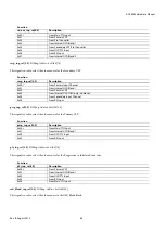
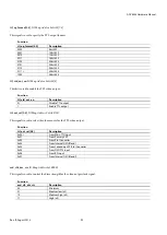
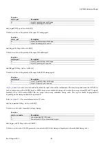
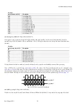
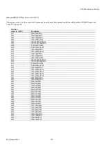
Function
vid_format_sel[4:0]
Description
0x00
1 x 8-bit bus, SDR 4:2:2
0x01
1 x 10-bit bus, SDR 4:2:2
0x02
1 x 12-bit bus, SDR 4:2:2
0x03
2 x 8-bit buses, SDR 4:2:2
0x04
2 x 10-bit buses, SDR 4:2:2
0x05
2 x 12-bit buses, SDR 4:2:2
0x06
3 x 8-bit buses, SDR 4:4:4 (P[35:28], P[23:16], P[11:4])
0x07
3 x 10-bit buses, SDR 4:4:4 (P[35:26], P[23:14], P[11:2])
0x08
3 x 12-bit buses, SDR 4:4:4
0x09
1 x 8-bit bus, DDR 4:2:2
0x0A
1 x 10-bit bus DDR 4:2:2
0x0B
1 x 12 bit bus, DDR 4:2:2
0x0C
3 x 8 bit buses, SDR 4:4:4 (P[23:0])
0x0D
2 x 3 x 8-bit interleaved buses, SDR 4:4:4
0x0E
2 x 2 x 8-bit interleaved buses, SDR 4:2:2
0x0F
2 x 2 x 10-bit interleaved buses, SDR 4:2:2
0x10
2 x 2 x 12-bit interleaved buses, SDR 4:2:2
0x11
3 x 10-bit buses, SDR 4:4:4 (P[29:0])
0x12
3 x 7-bit buses, SDR 4:4:4 (for external alpha blend)
0x13
3 x 10-bit buses, SDR 4:4:4 (OSD_IN[23:0] and P[35:30])
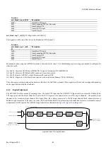
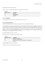
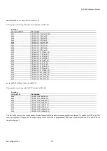
vid_swap_bus_ctrl[2:0]
, IO Map,
Address 0x1B48[7:5]
This signal is used to control the video input pixel bus. The input pixel bus is 36 bits wide and is divided into three data channels: Top =
D[35:24], Middle = D[23:12] and Bottom = D[11:0]. This register allows the user to swap the order of these three data channels.
Function
vid_swap_bus_ctrl[2:0]
Description
000
D[35:24] D[23:12] D[11:0]
001
D[35:24] D[11:0] D[23:12]
010
D[35:24] D[23:12] D[11:0]
011
D[23:12] D[35:24] D[11:0]
100
D[11:0] D[35:24] D[23:12]
101
D[11:0] D[23:12] D[35:24]
110
D[23:12] D[11:0] D[35:24]
111
D[35:24] D[23:12] D[11:0]
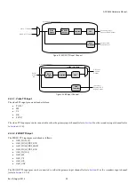
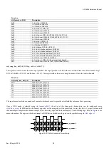
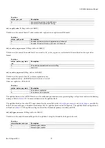
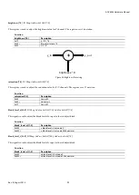
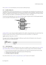
The input formatter also has a number of controls which can be used to provide extra flexibility in terms of data processing.
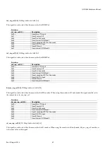
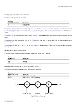
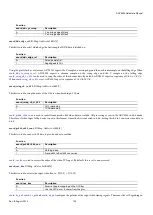
Once a DDR mode is selected using
, the order of the luma and chroma data can be configured using
. In DDR modes, the luma is expected on the rising edge of the pixel clock. Setting this bit to 1 swaps the luma and
chroma samples and places the chroma sample (C) on the rising edge and the luma sample (Y) on the falling edge. Refer to
more information. The edge on which each sample of DDR data is latched into the part can be specified using
Y
C
Y
C
Y
C
Y
C
C
Y
C
Y
C
Y
C
Y
ddr_yc_swap = 1
ddr_yc_swap = 0
Y
C
Y
C
Y
C
Y
C
C
Y
C
Y
C
Y
C
Y
ddr_yc_swap = 1
ddr_yc_swap = 0
Figure 34: DDR Mode, Luma and Chroma Swap
Summary of Contents for ADV8003
Page 366: ...ADV8003 Hardware Manual Rev B August 2013 366 Figure 144 ADV8003 Schematic Page 4...
Page 367: ...ADV8003 Hardware Manual Rev B August 2013 367 Figure 145 ADV8003 Schematic Page 5...
Page 368: ...ADV8003 Hardware Manual Rev B August 2013 368 Figure 146 ADV8003 Schematic Page 6...
Page 369: ...ADV8003 Hardware Manual Rev B August 2013 369 Figure 147 ADV8003 Schematic Page 7...
Page 371: ...ADV8003 Hardware Manual Rev B August 2013 371 Figure 149 ADV8003 Schematic Page 9...
Page 372: ...ADV8003 Hardware Manual Rev B August 2013 372 Figure 150 ADV8003 Schematic Page 10...
Page 373: ...ADV8003 Hardware Manual Rev B August 2013 373 Figure 151 ADV8003 Schematic Page 11...
Page 374: ...ADV8003 Hardware Manual Rev B August 2013 374 Figure 152 ADV8003 Schematic Page 12...
Page 375: ...ADV8003 Hardware Manual Rev B August 2013 375 Figure 153 ADV8003 Schematic Page 13...
Page 376: ...ADV8003 Hardware Manual Rev B August 2013 376 Figure 154 ADV8003 Schematic Page 14...
Page 377: ...ADV8003 Hardware Manual Rev B August 2013 377 Figure 155 ADV8003 Schematic Page 15...
Page 378: ...ADV8003 Hardware Manual Rev B August 2013 378 Figure 156 ADV8003 Schematic Page 16...
Page 379: ...ADV8003 Hardware Manual Rev B August 2013 379 Figure 157 ADV8003 Schematic Page 17...
Page 380: ...ADV8003 Hardware Manual Rev B August 2013 380 Figure 158 ADV8003 Schematic Page 18...
Page 381: ...ADV8003 Hardware Manual Rev B August 2013 381 Figure 159 ADV8003 Schematic Page 19...
Page 382: ...ADV8003 Hardware Manual Rev B August 2013 382 Figure 160 ADV8003 Schematic Page 20...
Page 383: ...ADV8003 Hardware Manual Rev B August 2013 383 Figure 161 ADV8003 Schematic Page 21...
Page 384: ...ADV8003 Hardware Manual Rev B August 2013 384 Figure 162 ADV8003 Schematic Page 22...
Page 385: ...ADV8003 Hardware Manual Rev B August 2013 385 Figure 163 ADV8003 Schematic Page 23...
Page 386: ...ADV8003 Hardware Manual Rev B August 2013 386 Figure 164 ADV8003 Schematic Page 24...
Page 387: ...ADV8003 Hardware Manual Rev B August 2013 387 Figure 165 ADV8003 Schematic Page 25...
Page 388: ...ADV8003 Hardware Manual Rev B August 2013 388 Figure 166 ADV8003 Schematic Page 26...
Page 389: ...ADV8003 Hardware Manual Rev B August 2013 389 Figure 167 ADV8003 Schematic Page 27...
Page 390: ...ADV8003 Hardware Manual Rev B August 2013 390 Figure 168 ADV8003 Schematic Page 28...
Page 391: ...ADV8003 Hardware Manual Rev B August 2013 391 Figure 169 ADV8003 Schematic Page 29...
Page 392: ...ADV8003 Hardware Manual Rev B August 2013 392 Figure 170 ADV8003 Schematic Page 30...
Page 393: ...ADV8003 Hardware Manual Rev B August 2013 393 Figure 171 ADV8003 Schematic Page 31...
Page 395: ...ADV8003 Hardware Manual Rev B August 2013 395 Figure 173 ADV8003 Layout Page 2...
Page 396: ...ADV8003 Hardware Manual Rev B August 2013 396 Figure 174 ADV8003 Layout Page 3...
Page 397: ...ADV8003 Hardware Manual Rev B August 2013 397 Figure 175 ADV8003 Layout Page 4...
Page 398: ...ADV8003 Hardware Manual Rev B August 2013 398 Figure 176 ADV8003 Layout Page 5...
Page 399: ...ADV8003 Hardware Manual Rev B August 2013 399 Figure 177 ADV8003 Layout Page 6...
Page 400: ...ADV8003 Hardware Manual Rev B August 2013 400 Figure 178 ADV8003 Layout Page 7...
Page 401: ...ADV8003 Hardware Manual Rev B August 2013 401 Figure 179 ADV8003 Layout Page 8...
Page 427: ...ADV8003 Hardware Manual Rev B August 2013 427 P 2 Z Z Z P 1 Z Z Z P 0 Z Z Z...

