UG-707
ADV8005 Hardware Reference Manual
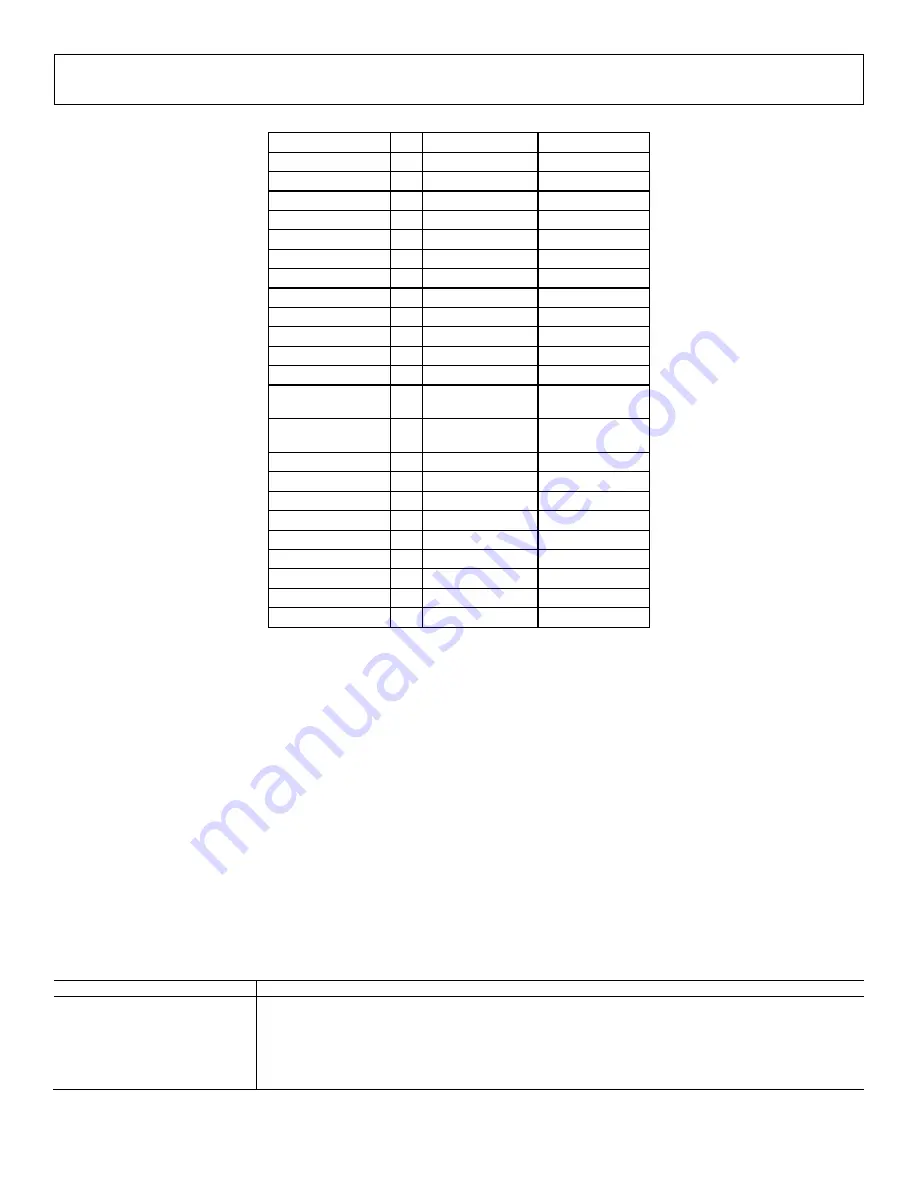
Table 70: Standards Directly Supported by
Encoder Processor
Active Resolution I/P Frame Rate (Hz)
Standard
720 × 240
P
59.94
720 × 288
P
50
720 × 480
I
29.97
ITU-R BT.601/656
720 × 576
I
25
ITU-R BT.601/656
720 × 483
P
59.94
SMPTE 293M
720 × 483
P
59.94
BTA T-1004
720 × 483
P
59.94
ITU-R BT.1358
720 × 576
P
50
ITU-R BT.1358
720 × 483
P
59.94
ITU-R BT.1362
720 × 576
P
50
ITU-R BT.1362
1920 × 1035
I
30
SMPTE 240M
1920 × 1035
I
29.97
SMPTE 240M
1280 × 720
P
60, 50, 30, 25, 24
SMPTE 296M
1280 × 720
P
23.97, 59.94, 29.97 SMPTE 296M
1920 × 1080
I
30, 25
SMPTE 274M
1920 × 1080
I
29.97
SMPTE 274M
1920 × 1080
I
25
SMPTE 295
1920 × 1080
I
50
ITU-R BT.709-5
1920 × 1080
P
30, 25, 24
SMPTE 274M
1920 × 1080
P
23.98, 29.97
SMPTE 274M
1920 × 1080
P
24
ITU-R BT.709-5
1920 × 1080
P
50
SMPTE 295
1920 × 1080
P
50, 59.94, 60
SMPTE 274M
I = interlaced, P = progressive.
7.3.
OUTPUT CONFIGURATION
Once the input to the encoder section has been configured, the user can configure the output of the encoder DACs. Depending on the input
mode specified by the
,
the DAC outputs can be configured accordingly using
It is important to note that if the
signal is set to simultaneous mode; then DACs 1-3 can only output the ED/HD signals of
YPbPr or RGB, and DACs 4-6 can only output the SD signals of CVBS or black burst or luma or chroma. It is possible to multiplex any of the
ED/HD signals out on any of the DACs 1 to 3 in simultaneous mode. Similarly, it is possible to multiplex any of the SD signals out on any of the
DACs 4 to 6.
It should also be noted that to enable the DAC outputs from the NON-ROVI
part (ADV8005KBCZ-8N) 00h must be written to
Encoder map, register 0xE4E0.
dac1_sel[2:0]
, Encoder Map,
Address 0xE429[6:4]
This signal selects the data that is supplied to DAC 1.
Function
dac1_sel[2:0]
Description
0 (default)
CVBS or Black Burst
1
Luma
2
Chroma
3
Y/G
4
Pb/B
5
Pr/R
Rev. A | Page 246 of 317


