ADV8005 Hardware Reference Manual
UG-707
vid_swap_bus_ctrl[2:0]
, IO Map,
Address 0x1B48[7:5]
This signal is used to control the video input pixel bus. The input pixel bus is 36 bits wide and is divided into three data channels: Top =
D[35:24], Middle = D[23:12] and Bottom = D[11:0]. This register allows the user to swap the order of these three data channels.
Function
vid_swap_bus_ctrl[2:0]
Description
000 (default)
D[35:24] D[23:12] D[11:0]
001
D[35:24] D[11:0] D[23:12]
010
D[35:24] D[23:12] D[11:0]
011
D[23:12] D[35:24] D[11:0]
100
D[11:0] D[35:24] D[23:12]
101
D[11:0] D[23:12] D[35:24]
110
D[23:12] D[11:0] D[35:24]
111
D[35:24] D[23:12] D[11:0]
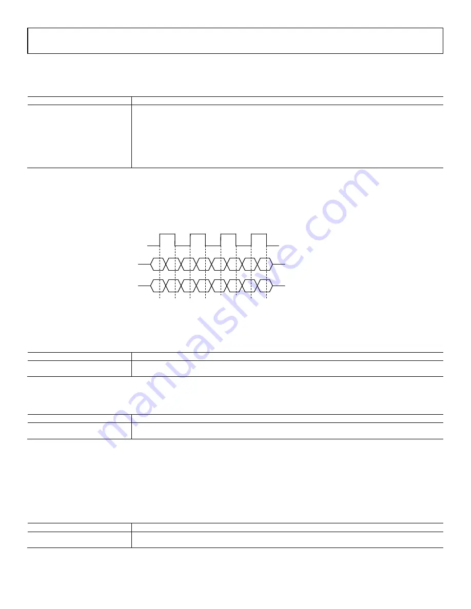
The input formatter also has a number of controls which can be used to provide extra flexibility in terms of data processing.
Once a DDR mode is selected using
, the order of the luma and chroma data can be configured using
. In
DDR modes, the luma is expected on the rising edge of the pixel clock. Setting this bit to 1 swaps the luma and chroma samples and places the
chroma sample (C) on the rising edge and the luma sample (Y) on the falling edge. Refer to
for more information. The edge on which
each sample of DDR data is latched into the part can be specified using
Figure 30: DDR Mode, Luma and Chroma Swap
vid_ddr_yc_swap
, IO Map,
Address 0x1B4A[0]
This bit is used to swap the Luma (Y) and Chroma (C) data in DDR modes. By default, Y is expected on the rising edge of the clock.
Function
vid_ddr_yc_swap
Description
0 (default)
Y on rising edge of clock
1
C on rising edge of clock
vid_ddr_edge_sel
, IO Map,
Address 0x1B4A[3]
This bit is used to select which edge the first sample of DDR data is latched on.
Function
vid_ddr_edge_sel
Description
0 (default)
Posedge data first
1
Negedge data first
Using the pixel clock as a reference,
expects the Y sample on a rising edge and then a chroma sample on the falling edge. When
expects a chroma sample on the rising edge and the Y sample on the falling edge.
can
be used to swap the order of the chroma data. By default,
expects a sequence of Cb, Cr, Cb, Cr… When
expects a sequence of Cr, Cb, Cr, Cb....
vid_swap_cb_cr_422
, IO Map,
Address 0x1B49[7]
This bit is used to swap the order of the C data when decoding 4:2:2 data.
Function
vid_swap_cb_cr_422
Description
0 (default)
Cb/Cr decoding
1
Cr/Cb decoding
is used to convert from pseudo 444 video data to real 444. All processing occurs in the
in 4:4:4 mode. Therefore,
Y
C
Y
C
Y
C
Y
C
C
Y
C
Y
C
Y
C
Y
ddr_yc_swap = 1
ddr_yc_swap = 0
Y
C
Y
C
Y
C
Y
C
C
Y
C
Y
C
Y
C
Y
ddr_yc_swap = 1
ddr_yc_swap = 0
Rev. A | Page 53 of 317


